- Home
- Product Categories
- RTC
- SparkFun DeadOn RTC Breakout - DS3234

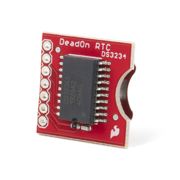
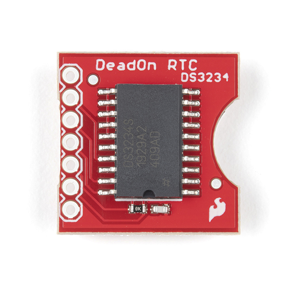
SparkFun DeadOn RTC Breakout - DS3234
Here is a real time clock based on the DS3234 Real Time Clock IC. The DS3234 is a low-cost, extremely accurate SPI bus real-time clock with an integrated temperature-compensated crystal oscillator and crystal.
The RTC maintains seconds, minutes, hours, day, date, month, and year information. The date at the end of the month is automatically adjusted for months with fewer than 31 days, including corrections of leap year. The clock operates in either the 24-hour or 12-hour format with AM/PM indicator. Two programmable time-of-day alarms and a programmable square-wave output are provided.
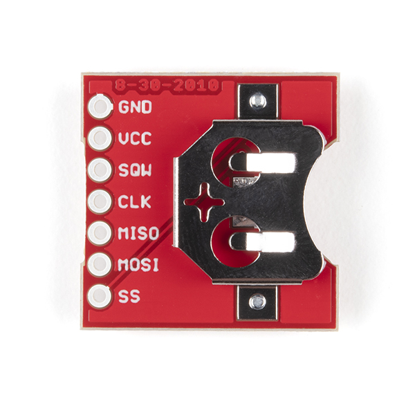
The underside of the board holds a 12mm coin-cell battery holder for battery backup.
Note: These do not include a battery. See the related products below for a battery.
- +-2ppm accuracy
- Two alarms
- SPI output
- Low power consumption
- Accurate calendar up to year 2100
SparkFun DeadOn RTC Breakout - DS3234 Product Help and Resources
DeadOn RTC Breakout Hookup Guide
October 6, 2016
An introduction to the DS3234 real-time clock (RTC), example wiring diagrams, and an Arduino library!
Core Skill: Soldering
This skill defines how difficult the soldering is on a particular product. It might be a couple simple solder joints, or require special reflow tools.
Skill Level: Noob - Some basic soldering is required, but it is limited to a just a few pins, basic through-hole soldering, and couple (if any) polarized components. A basic soldering iron is all you should need.
See all skill levels
Core Skill: Programming
If a board needs code or communicates somehow, you're going to need to know how to program or interface with it. The programming skill is all about communication and code.
Skill Level: Competent - The toolchain for programming is a bit more complex and will examples may not be explicitly provided for you. You will be required to have a fundamental knowledge of programming and be required to provide your own code. You may need to modify existing libraries or code to work with your specific hardware. Sensor and hardware interfaces will be SPI or I2C.
See all skill levels
Core Skill: Electrical Prototyping
If it requires power, you need to know how much, what all the pins do, and how to hook it up. You may need to reference datasheets, schematics, and know the ins and outs of electronics.
Skill Level: Rookie - You may be required to know a bit more about the component, such as orientation, or how to hook it up, in addition to power requirements. You will need to understand polarized components.
See all skill levels
Comments
Looking for answers to technical questions?
We welcome your comments and suggestions below. However, if you are looking for solutions to technical questions please see our Technical Assistance page.
Customer Reviews
4 out of 5
Based on 20 ratings:
1 of 1 found this helpful:
Good Hardware, but Arduino Support Has Issues
This hardware works as described. However, the Arduino IDE sets the time to the time that the Arduino IDE was launched, and not to the compile time when using the rtc.autoTime() library function. As long as you realize this and employ an adequate work-around (either set the time by other methods or quit/re-launch the IDE before compiling and uploading), then you should not experience any issues. The device itself works great.
1 of 1 found this helpful:
Cannot get it to work
Bought the DS3234 breakout board about 6 weeks ago. Still cannot get it to work. Library DS3234.h appears to be no longer available. Have tried several example sketches in the SPI.h library, none of which will compile without errors. Will continue to do research to see if I can get this thing to work.
The example from GitHub compiled properly for me. I would suggest that code to get started -- https://github.com/sparkfun/DeadOn_RTC/tree/v1.1
2 of 2 found this helpful:
Finally got it to work
If you're having trouble getting this to work, perhaps this will help.
I had to change the SPI Mode to 3 otherwise I just got random numbers for dates and times.
SPI.setDataMode(SPI_MODE3);
Device does a great job keeping time.
I've used this to set up a SNTP server using a ESP8266. It does a really good job of keeping time. If you are using it with a ESP-12 as I am, remember to set the SPI frequency (SPI.setFrequency()) to something <= 400,000. The datasheet says this device should be able to handle 2Mhz but I could not make it or needed it to work that fast.
UCT clock
Easy to use and accurate. I used a nano arduino and LCD to display the Universal coordinated time and the date. Set it with WWV and after three weeks still within 1 second.
What time is it? Time to buy one of these.
This thing is easy to use and keeps rock solid time. I'm using mine in an arduino clock project and it is working well.
Works well, but not with SD card so far...
I've got this working on a Mega with the Ethernet 2 shield, and it works fine including with the ethernet. So far, I'm not able to get it working with the SD card. I guess there's some SPI problem, but I can't track it down. I am aware of the need for different chip select pins. I'm using pin 4 for SD on the ethernet shield, pin 48 for the real time clock, and I'm setting pin 53 as an output so that the Ethernet 2 library is happy. Not sure what's going wrong yet. Seems like a good RTC and SD cards should be a common combination...
EDIT: I think the two libraries were configuring the bus in incompatible ways. I worked around this by simply initializing the connection each time I used it. I expect there are more elegant fixes, but this was fine for my purposes.
Mine seems to drift
Hooked up to my RedBoard and using most of the example as-is. I'm finding that it's running about five seconds fast per day. Is there anything I'm missing or is that the most accurate I can expect?
Hmmm, that seems excessively high. Is there any part of your circuit that may be creating excessive EMI near the DS3234? That could cause some issue. These are pretty solid, so I'd suggest contacting our tech support team. They should be able to help you out, or arrange a replacement.
time keeping is great, cant get the SRAM to work. Here is test code:
include <SPI.h>
const int cs=10; //chip select RTC
void setup() { Serial.begin(9600); RTC_init(); //day(1-31), month(1-12), year(0-99), hour(0-23), minute(0-59), second(0-59) // SetTimeDate(24, 1, 16, 17, 58, 00);
}
void loop() {
// Serial.println(ReadTimeDate());
delay(100);
StoreData();
} //=====================================
int StoreData(){ delay(100); digitalWrite(cs, LOW); delay(1); SPI.transfer(0x98);//Address? delay(1); SPI.transfer(0x04); //data at location aa? delay(1); digitalWrite(cs, HIGH); delay(50);
delay(100);
digitalWrite(cs, LOW);
delay(1);
SPI.transfer(0x99);//Address?
      delay(1);
SPI.transfer(0x05); //data at location ab?
delay(1);
digitalWrite(cs, HIGH);
delay(50);

delay(100);
digitalWrite(cs, LOW);
delay(1);
SPI.transfer(0x9A);//Address?
      delay(1);
SPI.transfer(0x06); //data at location ac?
delay(1);
digitalWrite(cs, HIGH);
delay(50);

delay(100);
digitalWrite(cs, LOW);
delay(1);
SPI.transfer(0x9B);//Address?
      delay(1);
SPI.transfer(0x07); //data at location ad?
delay(1);
digitalWrite(cs, HIGH);
delay(50);


delay(100);
digitalWrite(cs, LOW);
delay(1);
SPI.transfer(0x9C);//Address?
      delay(1);
SPI.transfer(0x08); //data at location ae?
delay(1);
digitalWrite(cs, HIGH);
delay(50);
int aa=99;// reset aa-ae int ab=99; int ac=99; int ad=99; int ae=99;
digitalWrite(cs, LOW);
   delay(1);
SPI.transfer(0x18);
aa= SPI.transfer(0x00);
      delay(1);
ab= SPI.transfer(0x00);
      delay(1);
ac= SPI.transfer(0x00);
      delay(1);
ad= SPI.transfer(0x00);
      delay(1);
ae= SPI.transfer(0x00);
      delay(1);
digitalWrite(cs, HIGH);

Serial.println(" ") ;
Serial.print(" o = ") ;  Serial.print(aa) ; Serial.println("   ") ;
Serial.print(" 1 = ") ;  Serial.print(ab) ; Serial.println("   ") ;
Serial.print(" 2 = ") ;  Serial.print(ac) ; Serial.println("   ") ;
Serial.print(" 3 = ") ;  Serial.print(ad) ; Serial.println("   ") ;
Serial.print(" 4 = ") ;  Serial.print(ad) ; Serial.println("   ") ;
Serial.println("   ") ;
}
int RTC_init(){
pinMode(cs,OUTPUT); // chip select
// start the SPI library:
SPI.begin();
SPI.setBitOrder(MSBFIRST);
SPI.setDataMode(SPI_MODE3); // both mode 1 & 3 should work
//set control register
digitalWrite(cs, LOW);
SPI.transfer(0x8E);
SPI.transfer(0x60); //60= disable Osciallator and Battery SQ wave @1hz, temp compensation, Alarms disabled
digitalWrite(cs, HIGH);
delay(10);
}
//=====================================
int SetTimeDate(int d, int mo, int y, int h, int mi, int s){
int TimeDate [7]={s,mi,h,0,d,mo,y};
for(int i=0; i<=6;i++){
if(i==3)
i++;
int b= TimeDate[i]/10;
int a= TimeDate[i]-b*10;
if(i==2){
if (b==2)
b=B00000010;
else if (b==1)
b=B00000001;
}
TimeDate[i]= a+(b<<4);
    digitalWrite(cs, LOW);
    SPI.transfer(i+0x80);
    SPI.transfer(TimeDate[i]);
    digitalWrite(cs, HIGH);
}
}
//=====================================
String ReadTimeDate(){
String temp;
int TimeDate [7]; //second,minute,hour,null,day,month,year
for(int i=0; i<=6;i++){
if(i==3)
i++;
digitalWrite(cs, LOW);
SPI.transfer(i+0x00);
unsigned int n = SPI.transfer(0x00);
digitalWrite(cs, HIGH);
int a=n & B00001111;
if(i==2){
int b=(n & B00110000)>>4; //24 hour mode
if(b==B00000010)
b=20;
else if(b==B00000001)
b=10;
TimeDate[i]=a+b;
}
else if(i==4){
int b=(n & B00110000)>>4;
TimeDate[i]=a+b10;
}
else if(i==5){
int b=(n & B00010000)>>4;
TimeDate[i]=a+b10;
}
else if(i==6){
int b=(n & B11110000)>>4;
TimeDate[i]=a+b10;
}
else{
int b=(n & B01110000)>>4;
TimeDate[i]=a+b10;
}
}
temp.concat(TimeDate[4]);
temp.concat("/") ;
temp.concat(TimeDate[5]);
temp.concat("/") ;
temp.concat(TimeDate[6]);
temp.concat(" ") ;
temp.concat(TimeDate[2]);
temp.concat(":") ;
temp.concat(TimeDate[1]);
temp.concat(":") ;
temp.concat(TimeDate[0]);
return(temp);
}
This looks like a great question for our tech support team. Hit them up, they can probably help you get this sorted!
Pretty slick little breakout
Easy to set the time on. Been running for a little while and has kept perfect time. Would recommend to anyone wanting a very good all around RTC.
Works great
Keeps good time. Easy to use. Well documented, with plenty of sample code.
I have previously used a DS1305 clock and similar ones which worked well, but this is better because its only 2cm and contains everything, Temperature compensated oscillator and clock all on one chip. I wrote my own Arduino library. Took about a week and a half to get it to work. Several syntax errors in my code. Fixed the code and works fine now. One thing I don't understand is the Enable oscillator bit 7 in the control register. (0eh/8eh) Page 14 of the DS3234 datasheet says "the oscillator is always on regardless of the status of the EOSC bit." So what's the purpose. I thought the oscillator should be off when setting the time? A bit expensive, but worth it if you need a small reliable, accurate clock for your project.
My new favorite RTC
I built an alarm clock with this, an atmega168, a piezo buzzer, an oled screen, and some buttons. The datasheet is very well written and it was easy to interface with the mega's builtin spi. The only issue I had was the clock was running 3 minutes fast every day until I added a 0.1uF decoupling cap.
Great product.
The board works well, I would have liked pin labeling on both sides of the board, but there may not be room for it.
Very accurate, be careful in noisy circuits
I've own this for a few months and am using it with dual 7-segment displays running off shift registers. At first, after a day, the clock would be up to 10 sec fast after being sync'd with time.gov. Apparently between the SPI interface and my shifting interface, the circuit was quite noisy causing the RTC to lose accuracy. Adding 0.1uf decoupling capacitors fixed the issue. Now the clock very accurate. The odd thing, though, is I see the breakout has a capacitor build into it so I'm not sure why that wasn't enough.
Good chip - don't be mislead by the demo code
I tried using the supplied demo code to check out the device. As several others observed, I found the clock was gaining about one second each 100 minutes - well beyond spec. After a bit of troubleshooting, I think the problem is not the chip but the demo code. That code sits in a tight loop calling rtc.update(), so it is reading the registers in the device hundreds of times per second. This seems to cause the chip to run fast. My real code reads it once per minute and it seems to be keeping much better time. Same was true with the demo code when I just disconnect the SPI bus - either with 5v power or on-board battery backup. Now I only call rtc.update() when there is an interrupt signal.
I know several others found the need for a bypass cap. That didn't help in my case.
Thank you for the feedback! If you could file an issue on the github page for the DeaOn RTC repo we can take a look and fix the issue: https://github.com/sparkfun/DeadOn_RTC/issues
0 of 1 found this helpful:
Works well!
I've not yet done any long term testing, but the simple example code Sparkfun provided worked and I'm currently up and running.
Works like a charm
I was having problems with an arduino based data logger that came with an RTC. The RTC kept going off to completely incorrect times and dates, which pretty much rendered the whole idea useless. I went ahead and replaced the RTC portion of that data logger with this DeadOn RTC from Sparkfun, and it works just as it should. Now my data logger always has the correct time stamps logged with the data.
To Power or not to Power?
It keeps excellent time. Whether it is powered from Vcc or Vbatt. Does everything it says it will. There are several libraries that work well.
DeadOn
Keeps excellent time . Mine has been running for about 6 months and is off only about 10 seconds .
The SparkFun DeadOn RTC Breakout - DS3234 board is good, BUT... it has the IC with the Operating Temperature Ranges of: Commercial: 0°C to +70°C, so it fails for me outdoors. Can I order boards with the Industrial: -40°C to +85°C chip?
HI
I would like to use your forum (which isn't finished? Why var names in form fields?) However, I already have an account, but don't know what my username is, and there doesn't seem to be a way to retrieve it!
Regarding the alarms, is there a way to program the device that the alarms don't make any noise, and that when the alarms time hit, they trigger something to happen?
I'm not sure what's going on with this but I'm on my second DS3234 that is running 15 seconds fast within 2 days. By the end of the week it's about a minute and half fast... It's either a bad batch or my code is effecting it which I don't understand how because all I'm doing is reading the time to display to a 7 segment.
Does anyone know how to increment the hours without it falling out of 12 hour mode? I'm using the <SparkFunDS3234RTC.h> library and the setHour command seems to be the culprit. Is there a way manually set the AM/PM bit? Here's my function:
Using the Arduino Library's rtc.autoTime() I seem to get strange values for time, instead of syncing to the time on my computer, it displays 0:16:45 | Sunday - 1/1/0
Then I tried to set the time using function rtc.setTime(second, minute, hour, day, date, month, year), with all the parameter variables predefined, I was able to print the newly defined time but when I use rtc.update() function to update the time it goes back to 0:16:45 | Sunday - 1/1/0
Any suggestions on how to fix this?
Is this a scam or what? The recommended 1225 battery doesn't fit. The device actually uses a 1220.
Sorry you had problems with the holder. The only difference between the size of the 1225 and the 1220 is 0.5mm in height. This battery holder should fit most 12mm diameter batteries and we've used without problem with the 1225s. It is possible your board got a bit smashed during shipping making it harder to fit the 1225 in the slot. If you have any concerns on the board please feel free to contact our techsupport department.
I'm trying to understand how the library got SPI.Transfer(0x8e); // Control register then line down it says, SPI.Transfer(0x60); // disables square wave......alarm clock.
I looked through the data sheet to find where the 0x60 came from. Did they mean to transfer to the 6th bit of 0x8e register? That messed me up pretty bad at trying to understand SPI Programming. Anyone know?
This code is written in assembly, but may help some: github.com/cat-tech/DS3234RTConPIC16F88. I had some issues getting the RTC stay on time during power up. I suspect the /CS does not properly clear the SPI buffer when inactive. Perhaps it is just my device? Having knocked the code into shape, it seems to be working very well, and keeping good time. Also, can't leave a review? Is that because I did not buy the board direct from Sparkfun, but through a local reseller?
This RTC works GREAT with the raspberry pi, but it isn't automatic by any stretch.. at least in current versions of Raspian.. There's a great article here: http://www.sciencegizmo.com.au/?p=137
This is the article I followed, and it got me to the point that my Pi was seeing /dev/rtc, and was working great with the hwclock executable.
Good luck! Steve
Great board. Great part. I have it working solid on a STM32F4 using DMA. 33us to read the time and date! Not bad.
One observation I have and I'm just wondering if anyone else has seen this. The very first read after startup comes back wrong by anywhere from 2 to 6 seconds. Every read after that comes in perfect. The datasheet says the buffer registers are sync'd on the falling edge of /CS but that doesn't seem to be the case for the very first read.
Anyone else?
Looks like the first read can also be complete garbage. I've noticed that all I have to do is toggle the /CS pin and the first read after that will be fine. Very reproducible.
Ok. Got it. The /CS pin was not being set high at startup. I had commented that line out by mistake when I commented out a whole block of code. First read is working properly.
There is a tutorial online on using the DS3234 breakout with Arduino => http://www.l8ter.com/?p=375 . Make sure that users connect to the SPI pins, 5V power, and the SQW pin to GND:
If you see this type of output:
it's possible that there is a loose connection between the breakout board and the Arduino. SPI communication is sensitive to bad connections. Try double checking the connections.
Why are you telling people to tie the SQW pin (which is an output) to GND? Granted this is an open drain output so grounding it shouldn't hurt it. Here is what the datasheet says about the pin:
If you aren't using it, just leave it unconnected. It's a bad habit to tie unused outputs to ground. It's the unused inputs that should be tied either to ground or VCC.
I created an implementation of JeeLabs RTClib for this unit. It's posted on github.
Thanks for creating this library!! It helped a lot!!
One thing I would add, is that you need to set the SPI data mode back to MODE0 after using this library if you are also using the SD card and the ethernet shield.
Also, make sure you aren't trying to access the clock while you have a file open on the SD card. I check the time, check for HTTP requests, and then serve a file. It seems you can get away with accessing the ethernet chip while files are open, but the RTC doesn't work that way.
I use the following functions:
DateTime check_time()
{
}
I encountered a similar issue trying to use the sparkfun example with an SD card. In my case, I was using the DeadOn RTC and sparkfun example with the sparkfun microSD shield stacked on top of an arduino uno r3. I was initially only able to get either the SD or RTC working at any time despite an hour of troubleshooting.
Eventually I came to this comment and changed the ReadTimeDate and SetTimeDate functions (added the two lines below at the beginning/end of the functions) to take care of the SPI mode switching, and everything works great!.
I also changed this line, as the SD chip select is pin 8
Finally, I changed the date format to yyyy-mm-dd hh:mm:ss including 0 placeholders for single digit values, which is much more useful to me:
Hey just wanted to say thanks for the library you posted. I really appreciate it as i am new to all this and was having trouble getting this clock talking with the whole SPI thing then realized the RTClib i had was wrong and meant for a DS1307. After adding your RTClib everything worked perfect! Seeing the differences I now understand a lot more about the arduino environment. I can't thank you enough!
Seriously, $20 and no battery included? Why?
ALL the other RTC's I've purchased from SFE included a battery. What's different? My fault for not noticing... but really?
Twice the price of else where! Why?
Just to put things in perspective, +-2ppm is 2 seconds in 11.57 days or one minute in 347 days. Or just about one minute per year.
For a simple crystal RTC, this is great. For a highly accurate timepiece it is marginal. If accurate time is your holy grail, then a GPS or radio time piece might be a better choice. In those cases you get tied back to the world time standard and will not suffer drift.
I hope you agree with me that it is +- (plus or minus) 2ppm. this means that drift can occur in both directions, so what you are sketching is a worst case scenario.
My math comes up with different numbers. +/-2ppm = 2E6, there are 60 sec/min, 3600 sec/hr and 86400 sec/day. 2E6 divided by 86400 sec = 23.148148 Days. Therefore if the error remained constant at plus or minus 2ppm it would take 23 days, 3 hrs, 33 min and 20 sec to gain or loose 1 sec repectively.
I think there is something wrong on those numbers! ppm stands for parts-per-million (10E-6) so +/-2ppm is +/-2E-6 or +/-0.0002% of error.
The error after one day will be 0.0002% of 86400 sec = 0.1728 sec To have 1 second it only needs 5.787 days! And this will be true if the device is operating at ambient temperature (25ºC). If not then the temperature should be taken into account!
Maxim has a nice Real-Time Clock Calculator for ppm ( http://www.maxim-ic.com/design/tools/calculators/product-design/rtc.cfm ), check it out!
Sorry, I wasn't pay attention to what I was reading. 2 seconds in 11.57 days = 1 second in 23.14 days, therefore my math does agree with your numbers. Can I chalk it up to a long day?
Ive just got mine going, and I'm losing about 3 seconds per day right now... This is totally unacceptable! Has anyone else had an issue like this?
Yes - this great for small projects, or beginners though, and easier to use. It's perfectly good for things that don't need to be at an exact time, but around the same time.
Last year, I customized RTClib to work with the DS3234, including alarms, clock-setting functionality, and more. Just realized I never posted it anywhere. Here you go, enjoy!
https://github.com/NorthernWidget/RTClib
And ask questions if you have any.
The datasheet of the DS3234 says "low-cost", which is a joke, of course. The IC costs 10 dollar at Digikey (in ones). Granted you don't have to pay for the crystal separately, but that only costs 21 cents (in ones). The PCF85263A can achieve the same accuracy through a calibration register and costs 99 cent (in ones).
In quantities, the PCF85263A + crystal cost less than 60 cent.
I've updated @maniacbug's RTC library with clock setting functions, a SPI_MODE3 fix (noted here), alarm functionality, and a few other changes. Check it out on github. Cheers!
Hello, I’ve two DS3234 connected to two different Arduinos, I followed this tutorial http://www.l8ter.com/?p=375 one of them works perfectly but the other show me the following in Serial monitor:
10/10/10 10:10:0 11/11/11 11:11:11 12/12/12 12:12:12 13/13/13 13:13:13 14/14/14 14:14:14 15/15/15 15:15:15 16/16/16 16:16:16 17/17/17 17:17:17 18/18/18 18:18:18 19/19/19 19:19:19 20/0/20 20:20:20 21/1/21 21:21:21 22/2/22 22:22:22 23/3/23 23:23:23 24/4/24 24:24:24 25/5/25 25:25:25 26/6/26 26:26:26 27/7/27 27:27:27 28/8/28 28:28:28 29/9/29 29:29:29 30/10/30 3:30:30 31/11/31 4:31:31 32/12/32 5:32:32 33/13/33 6:33:33 34/14/34 7:34:34 35/15/35 8:35:35 36/16/36 9:36:36 37/17/37 10:37:37 38/18/38 11:38:38 39/19/39 12:39:39 0/0/40 0:40:40 1/1/41 1:41:41 2/2/42 2:42:42 3/3/43 3:43:43 4/4/44 4:44:44 5/5/45 5:45:45 6/6/46 6:46:46
It seems that every second increase all records in one unit, if I only read every 5 seconds they increased 5 units. Could it be a wiring or soldering problem or is the DS3234 damaged?
Best regards.
That particular code has an error. The line which reads
should really read
It is true that the manufacturer's data sheet claims that SPI should work in both modes 1 and 3. However, I have found that, in practice, SPI only works in mode 3 with the chip. That problem may not necessarily be a problem with the manufacturer. The problem may lie with the SPI library itself.
A lot of thanks AllanStarSoftware the problem was a bad connection with MOSI pin.
This code is extra confusing for no apparent reason, took me awhile to mash it out. Ah BCD, I'm an idiot.
... just now able to set the time and date on this thing using an Arduino Uno and V1.01 of the IDE. The example sketch provided by Sparkfun on the product page was helpful, but don't believe everything you read. The sketch has a comment indicating that it will work in either SPI mode 1 or mode 3. This same idea appears in the datasheet for the device. I was only able to set the time/date by changing the example code's setDataMode command to "SPI.setDataMode(SPI_MODE3);". Using SPI_MODE1 resulted in seemingly nonsense numbers going to the serial monitor.
MFindley,
Are you saying you finally got the date/time to set? That's the one thing I'm struggling with now. Using both the library above and the example sketch (modified to SPI_MODE3) I can read date/time no problem, but can't seem to set it no matter what. Mind sending me you sketch?
And after hours of playing around, it appears as though the my RTC in combination with the 1.01 compiler won't take a time unless Vcc is given 5V and the SPI is set to MODE3. The 3.3V pin only allows me to read off of the RTC.
I have this hooked up to an Arduino Uno board, and can set and read time with no problems, although things only work in SPI mode 3.
Next I tried to get the SQW pin to trigger an interrupt on the Arduino every second, and that's where I'm not getting things to work. Hoping someone can help me.
I hooked up Arduino pin 2 to SQW, and added a 4.7K resistor from SQW to Vcc. In my sketch, I do pinMode(2,INPUT) and then hook up the interrupt function. I then set register 0x8E to 0x60. I was expecting the interrupt to fire once a second, but it never does.
If I disconnect the connection to SQW and move by hand touch it to GND, the interrupt fires as I would expect.
I unfortunately do not have a scope or logic analyzer handy... I'd appreciate any insight on what I'm missing here.
Niels.
... thanks for the tip on using SPI mode 3.
Must use 3.3v VCC, instead of 5.0v VCC used in the above Example Sketch, otherwise square wave output doesn't work.
Must use SPI_MODE3, instead of Mode 1, otherwise one line correct time, followed by one line 00/00....
One more post: I spent a couple of hours getting the interrupt to work this morning. Two pieces of info that may be of use-- (1) The output of the square wave pin on the ds3234 cannot be tied directly to the input of an Arduino. A 4.7K resistor seemed to work fine. (2)You may need to build a delay into your code between detecting a square wave and reading the registers to let the update complete.
Does this work with Arduino?
And also, how specifically should I wire it up?
Yes.
Just wired it up like this.
Pin 13 SCK
Pin 12 MISO
Pin 11 MOSI
Pin 8 SS
Also i had to change a line in the example code to be able to set the time.
SPI.setDataMode(SPI_MODE3); // Mode1 didnt work
I have mine wired as Pin 13 CLK (there's no pin marked SCK on the RTC board) Pin 12 MISO, Pin 11 MOSI, and pin 8 SS. Using the example code, I tried MODE1 and MODE3 and both result in the following being displayed:
45/25/165 18:85:85
or
0/0/0 0:0:0
Any ideas? Thanks.
Check on the second line of the example code, that the "cs" constant has the same number with the pin that you connect the "ss" pin on the DS3234
I was experiencing the 45/25/165 18:85:85 / 0/0/0 0:0:0 issue as well. Turns out I had the wiring wrong (I'm a beginner). I'm using the Mega 2560 and I have it wired up as follows:
GND - GND
VCC - 3.3v
SQW - GND
CLK - 52
MISO - 50
MOSI - 51
SS - 8
battery is attached
It now works with both Sparkfun's example and maniacbug's library (which is awesome!).
I am having the same issue.
Wired the RTC up like above but neither MODE1 nor MODE3 are giving a different result from 0/0/0 0:0:0
Also tried using RTClib as suggested in this thread.
Possibly a defective part?
I would recommend soldering on some break away headers to make sure the connection to the chip and your breadboard is solid. I had the same issue but this solved it.
You could also get some Solderless Headers.
Yes this works with an Arduino, please see the Example Code. I just named it .c instead of .pde for display in notepad++. As for wiring please check http://www.arduino.cc/playground/Code/Spi. With the exception of SPI slave select which is pin 8 in the Example Code that page should help.
That does - Thanks!
Are there any issues using this with a 3.3V micro? I have integrated this with a logomatic via the SSP1 and it works pretty well 99% of the time but sometimes I fail to clear the alarm flag - when this happens repeated writes don't make much difference
See the DS3234 datasheet. It likes Vcc = 3.3V but will also take 5V.
Why is the decoupling capacitor in the schematic only 22pF? The datasheet calls for 0.1 to 1.0 uF. Is that an error in the schematic? Do the shipped boards have a 22pF or 0.1uF cap?
Does it compensate for DST (Daylight Savings Time)?
No, not by itself.
Because the DST rules are different in different countries (and sometimes different within portions of the same country) and subject the the whims of what ever politicians are in charge, it would make no sense to hard-code the rulesets into silicon. There is a DST library available for Arduino (I forget the site and don't have time to Google it for you), or you can simply code in the rules for the target location where you plan to deploy your clock.
Looking for some assistance on how to interface this RTC module to a BeagleBone Black running Debian. I would like to use it as the hardware RTC and update the system time/date with it. I have lots of experience with hardware and firmware, but very limited Linux knowledge. I have found bits and pieces of information, but not enough to make it work.
I assume that I have to load/unable the rtc-ds3234 driver in the kernel, but I don't know how to do this.
I can't seem to find the info to be able to assign the correct pins from the RTC to the BBB.
Any help would be appreciated.
Something doesn't add up. Either it is the comment or the action. Line 25: "SPI.transfer(0x60); //60= disable Oscillator and Battery SQ wave @1hz, temp compensation, Alarms disabled"
Why are we disabling all these things. Is that permanent. also is there any using them?
Where do I find/buy the battery for this device?
Right here!
I need some help modifying the code to set the DS3234 to the current time. Thanks.
I also have a driver for this board: GitHub DS3234 Note that this driver does not need to use the Arduino SPI... it can use any pins you wish.
I'm having serious issues getting this working with Arduino Due. I'm using the ICSP pins broken out on the board with the SS connected to D53 (made the appropriate change in the example sketch). When I run the sketch I get "45/25/165 18:85:85" with no incrementation. I have read the data sheet and tutorials, as well as trying the RTC library (doesn't work with the Due). I'm at a loss as to what I'm screwing up. Please help!
The Due has an ICSP and an SPI-Header. Use the SPI-Header. There is a little dot ahead of the word "SPI". There is Pin 1 with MISO, Pin 2 is at the "I" of the "SPI"... and VCC The othe Pins you can see at ICSP-Pinout. "SS" of the RTC I've put on digital Pin 8.
Be sure have loaded the the Arduino 2 compiler and at tools board "Programming Port due" and at port the one where the usb is plugged in.
Going this way it works.
Were you able to resolve this? I'm hitting my head against this issue on the Arduino Micro.
I am having some trouble. Got it hooked up to Uno Gnd-gnd Vcc-5v Int/Skw-Gnd SLK-pin 13 Miso-pin 12 Mosi-pin 11 SS-pin 8 with the code set at Mode 1 or 3 The date and time display but it doesn't count, .... it just repeats the same information. any ideas?
Does anyone know of an easy way to set this up so it just counts upward starting with zero seconds at the time it is turned on?
Initially I could not get the control register to set using the example sketch. After a lot of troubleshooting I found the problem was that in the example code the CS pin is never set HIGH before going LOW for the initialization transmission. In that case the RTC doesn't see the falling edge and doesn't listen to the command.
It seems to me that the example sketch has a confusing initialization state. It is set to transmit 0x60, which looks like it sets the oscillator enabled, BBSQW to logic 1 (SQW on when in battery mode) and the temp conv to logic 1 (forcing one immediate user-initiated temp conversion). I don't know if that was the intended setting based on the code's comments and the data sheet.
I set my control register to 0x00 which sets: oscillator enabled, a 1 Hz square wave (when normally powered, and SQW off in battery mode) and alarms off. If a square wave is not desired, then the control register could be left in the default condition with no ill effects.
It is written in the "Note" than the battery is not include but then in the "Features" than the battery is include??
It might be cool to switch the 12mm lithium primary cell out for a rechargeable battery. Connect a series diode and 1.1k resistor from Vdd to recharge the battery. An SMT rechargeable like a Panasonic ML-621S/DN would work well. You could keep a few more batteries out of landfills that way and the clock would still stay set for about a month unplugged.
Hi Do you know a full Arduino library for this? That prints time, temperature. Allows to change time and set both alarms. Thx
Hi, I have an Arduino Mega 2560 R3 and this LCD shield with 5 buttons : http://www.teguna.ro/produse/Shield-Arduino/shield_LCD_tastatura My shield occupies and uses pins 8->13 so I tried to use the example mentioned bellow: 50 (MISO), 51 (MOSI), 52 (CLK), 53 (SS), GND & SQK grounded, VCC to +5 but without any luck. The clock is working Ok on my other Arduino Uno but I can't seem to be able to make it work on my Mega + LCD shield. Can you please help ?
What or who is DeadOn? It would also be nice if it had some M3 holes, because I use M3 screws in my designs.
CodeVisionAVR library for DS3234 http://www.avrfreaks.net/index.php?module=Freaks%20Academy&func=viewItem&item_type=project&item_id=3864
If I don't ever intend to use the INT/SQW pins, can I omit the 10k resistor and the 22pF cap? Or does the VCC depend on this part of the circuit?
does this work at 3.3v?
Is there any reason why pins 3 and 6 are not broken out? They are RESET and 32kHz respectively... seems like you're just throwing away functionality for no reason whatsoever... What am I missing?
I recently purchased one of these and am using it in clock. However I find it is somehow gaining time on the order of 10 or so seconds over the course of a few hours. This is clearly more that the 2ppm listed in the spec sheet. I'm not sure how this is happening since I am not writing to the chip so I assume that the RTC chip is not accurate. Is it possible for the DS3234 to drift this much so quickly?
Dunno, but regarding to my earlier post, accuracy seems to be pretty good in long term scale. It may fluctuate more than 2 ppm on a single day, but overall stability seems to be far more better instead of extrapolating the drift based on per one day. RTC is near of my window and I’ll open it pretty regularly. I haven’t studied how much temperature fluctuations will affect to the total accuracy. 10 secs sounds still kinda a large drift. May that be some kind of EMI related issue of your circuitry? High SPI-frequency and continuously polling may generate some extra pulses to the clock source. At least INT-pin was affected by SPI-data when scoping of my case.
I have purchased couple of these modules. Nice product especially if SPI is already utilized on your MCU. However extremely accurate seems to be just accurate in my case. Maybe I’m doing something wrong like using 512 conversion sample rate instead of 64. I have Maxim's DS3231M evaluation board which seems to be very accurate as the chip has been run several months with less than one second deviation. These DS3234 modules will deviate about one sec per day which is ~6 minutes/year.
I have written library with CVAVR and i'm not quite sure how to interpret the datasheet. One is Conversion sample rate seconds. Is this calibration interval or samples per second? I mean should CRATE0 and 1 bits set to zero? Another issue is temperature values below zero. I'm unable to get correct negative values when getting the chip from freezer. Two's complement value has been noticed, but is the commercial version of the RTC unable to display temperature values below zero?
Is it possible to get one of these preprogrammed to the time being transmitted from Fort Collins, Colorado By WWVB (and even better delivered before it gains or looses a full second….)?
Without a battery installed, it won't keep the time during shipping. (Battery sold separately)
any chance of sparkfun doing a breakout for the ds3232. Why do only those who use SPI get to use a more accurate clock?
Hi, I was wondering if someone could help me understand how to interpret the SPI.transfer function values in the example sketch. I assume that they relate to Figure 1 in the datasheet but don't know how to translate the hex values 8E and 60 into the values in the table. Also, it seems to me that the day and month variables in the setTimeDate function are in the wrong order (i.e., the first variable is the month and second is the day). Thanks for any help.
Has anyone managed to use this to add a hardware clock to a Raspberry Pi?
I have managed to get the SPI working, I have found I can sudo modprobe rtc-ds3234 but I am not clear on how to tell the kernel that the SS pin is connected to CE0 on the GPIO so that the rtc-ds3234 can access it.
Help!
Hello, I don't have this thing yet, I am wondering if it's worth buying it instead of the DS1307. Because in the code I see the temperature compensation is disabled (probably for a good reason), that mean it won't be more accurate than the DS1307, correct?
Hi. I am using a pic 18F14K50 with this RTC module. I am connecting the RTC with no battery directly to the PIC via SPI. I would like to know if I have to set anything else. My reception routine is : char getByte(char data){ char var; SPI_CS = 0;
putcSPI(data); //Send command var = getcSPI(); //receive data SPI_CS = 1;
return var; }
im considering making a watch with this and i need to know how thick is this with and without the battery holder? preferably in metric
Has anyone tried to interface this RTC with an MSP430? I am having a really hard time doing so... Using the Arduino code as a flowchart i was able to produce a c code for the msp, but I get bogus readings from the RTC. Any help would be be appreciated.
Works fine for a while, then gets bad date somehow: 12/04/22-01:31:04 12/04/22-01:31:34 65/12/31-23:60:46 65/12/31-23:40:16 65/12/31-23:40:46
(first number is year ie 2012,2012,2065)
Any idea why this might happen? I am not setting the date, only reading it. But when I see that it has gone bad, I do set the date, and it is fine for a while again. Using arduino mega256, RTC_DS3234.h
i'm a bit partial to sparkfun, so before i buy, what are the differences between the chronodot 2.1 breakout and this ds3234 breakout?
i see the pins are a bit different, headers soldered on, a batt is provided, sram, i2c vs spi.
i guess its a matter of i2c vs spi and form factor & the price diff?
There are a couple minor differences (or major if your project depends on them...) in addition to I2C vs SPI:
Is there a way for me to change the clock from 24-hours to 12 hours?
page 11 of datasheet.
Can anybody explain what is the PIN SQW? I�ve never seen it? Thanks
Take a look at the datasheet (link above). This output pin can be configured to provide an interrupt signal (alarm, etc.), or a square wave (hence SQW) at various frequencies.
What I often use the SQW pin for is I set it as 1Hz (1PPS) and attach it as an interrupt. Then on the falling edge I set a flag. I then only regularly read the time if the flag is set. Yes, I can't use alarms with this technique, but I only have to spend the clock cycles to communicate and parse the response of the RTC once a second, instead of on every loop of my code.
Working fine on mega2560: RTClib.cpp needed <arduino.h> replaced with <Arduino.h>
50 (MISO), 51 (MOSI), 52 (CLK), 53 (SS), GND & SQK grounded, VCC to +5
include <Wire.h>
include <SPI.h>
include <RTClib.h>
include <RTC_DS3234.h>
RTC_DS3234 RTC(53);
void setup(){
SPI.begin();
RTC.begin();
RTC.adjust(DateTime(DATE, TIME));
SPI.setDataMode(SPI_MODE0);
Serial.begin(9600);
}
void loop(){ const int len = 32; static char buf[len]; DateTime now = RTC.now(); Serial.println(now.toString(buf,len)); delay(1000); }
Hey All --
I got my DS3234 working, in that I can set the time and read the time, however, the battery back up does not appear to be working. I've got it hooked up to an arduino uno and when I remove the unos power and let the chip sit for, say, 24 hours the time is no longer correct.
I've got a CR1225 battery that reads 2.9 V
Here is how I've got it wired:
*gnd -> gnd
*vcc -> 3v
*sqw -> gnd
*clk -> pin13
*miso -> pin12
*mosi -> pin11
*ss -> A0
Any thoughts?
EOSC bit was set to 1, please read page 10 and 12 of DS3234 datasheet.
You can alter EOSC bit by sending command to address 8Eh something like this:
digitalWrite(cs, LOW); SPI.transfer(8Eh); SPI.transfer(00011100b);
digitalWrite(cs, HIGH);
I had been using a DS1307, but the timekeeping was not as good as I had hoped. The DS1307 can easily drift by a minute a week. The DS3234 has, so far, stayed within 1 second per week. If you are data logging, I highly recommend the DS3234 over the DS1307. Check out openlog as well if you are into data collection. Openlog makes saving data very simple. The DS3234 makes the time that data is saved very accurate.
I'm lobbying for a PCF85263A breakout board. Way more features than the DS1307, though not the basic accuracy of the DS3234. The 85263A does have a calibration register, though, so you can compensate for the crystal base error. And the 85263A is really, really cheap!
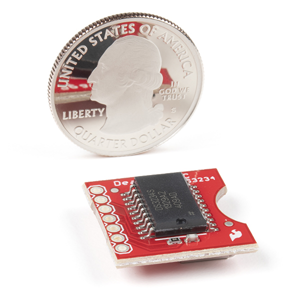
PacMan reference in image 4!
Hello All
I finally got this guy working. Ref http://www.l8ter.com/?p=375
for wiring and use the Example sketch.
Very weird. First the problem seemed to be the jumper wires I was using between my Uno and the breadboard were picking up "noise" - one wire in particular seemd to be most sensitive - the LOW tie down on the SQW pin - when I used a shorter wire it appeared to work ok but after 20 secs or so the output would appear to get corrupted and fix it self agian after another 20secs - I set SPI.setDataMode(SPI_MODE3) and it seemd to stabilze the o/p
Good Luck
Is there any way to make this work with a different coin cell battery? Because I don't have a CR1225...
I have 3x G8-A's
I have 9x 357's
I have 5x CR2032's
Someone can tell me what is going wrong.
I have used the DS1307 Engine for the propeller and now my dates don't work correctly. It uses impossible dates like september 31 and then jumps to october 2 the next day. ?
Any help is very appreciated !
This is not a DS1307 chip.
does the library work with the alarm?
There is something wrong with the newest version of the arduino ide (0022) and this example code. It calls the ReadTimeDate() one time and outputs it to the serial monitor as expected and it never calls it again. I don't have enough expertise to understand what is going wrong. I suggest someone with more know-how try compiling the example code in 0022 and note the results. I downgraded to 0021 in order to get this working. I don't know if the problem is a bug in the 0022 IDE or the code provided here. I would be curious to know if anyone gets it working in 0022, I haven't ruled out that the problem is exclusive to me/my system.
I had the same problem and did what you said, used 0021 and it works fine now.
Although, the original sketch worked for me. I had problems when changing the numbers sent with the SetTimeDate function. Sometimes it would output the ReadTimeDate correctly until it got to a certain time and would lock up.
For what it's worth, I had the same issue in Arduino 1.0.1. In the ReadTimeDate() function, the String 'temp' is not initialized; changing the first temp.concat() call to an assignment resolved this issue for me - e.g. 'temp=String(TimeDate[4])'; instead of 'temp.concat(TimeDate[4])';
Any idea how to (easily) calculate duration using this RTC? I can't track down a function that would let me subtract a start date and time from the retrieved date and time. I want something similar to:
duration = millis() - startTime;
Thanks!
I think maniacbug's port of JeeLabs RTClib (grabbed link from comment above) would help with with date calculations.
This was perfect. Thanks!
With a little bit of string manipulation, you could change the date and time into seconds.
Seems like that would be A LOT of string manipulation. There is no way of "easily" determining the the day number of the current year to be able to "easily" get to a unit of seconds. I would have to figure out what month it is, and then count, in a very specific way, to determine which day (0-364) it is. No? Am I missing something?
Perhaps a bit of help to a real new user. I bought the DS3234 and do have it running. I set the clock by entering it into the code supplied on this page. This only gets to clock close not exact. How can this clock be set to the current internet time? As a newcomer to C language coding, how can I reference the clock time in other programs? I need to trigger a camera during a specific time, as I photograph the space shuttle launches and need to listen for the sound of the launch during the time it may take place. I am using PLC's to do this in the past but want to try an Arduino triggger for the next launch (Images at MarkWidick.com) Thanks in advance.
http://arduino.cc/playground/Main/InterfacingWithSoftware Start there. I believe something like Firmata or GoBetwino would help you out. You may be able to just script something up using serial transmissions only. Needing the type of accuracy one would desire for such a one time only event I would think that GPS or radio would be better for you. Get your GPS time, if it matches the desired set time, take the pic.
Cancel that question. Half asleep this morning. I figured it out.
We would appreciate if you would share.
Some help, please. I intend to use the square wave output to trigger an interrupt on a uC. The datasheet says that this line needs a pullup resistor. The schematic for the board shows a 10K resistor and 22pf cap to ground from this pin. I presume that the 10k, since it is on the "high" side of the cap, is not an issue in terms of my pullup resistor.
So... a couple of questions from this newbie. The reference diagram on the datasheet does not indicate a need for this circuitry. Why is it there? Second, any suggestions for a pullup? I was thinking in the 4.7K range.
Thanks all.
Ed
It would be great if there was a revision of this which broke out the 32kHz pin - since that can feed the async timer of an AVR for sub-second RTC on the AVR.
(I hadn't realised at all the CLK pin is the SPI clock. Yeah, kinda obvious now I look at it.)
Is there any chance the next batch of these could be produced using the DS3234SN part instead of the DS3234S? This product would be much better if it could operate in the industrial (-40°C to +85°C) temperature range.
The macetech ChronoDot2.0 is made with the DS3231SN, which has the operational range of -40 to 85 deg C. See above post.
http://macetech.com/store/index.php?mainpage=productinfo&products_id=8
Actually, I have been debating between the ChronoDot2.0 with it's i2c interface, extended temp range and the lower cost, and the Sparkfun DS3234S based module with the sram and SPI interface. Either module would be excellent, but it would be nice if Sparkfun would produce two versions of 3.3volt RTC modules, one based on the DS3231SN for the i2c fans and a second version based on the DS3234SN for the SPI fans. ChronoDot, well, I guess I am a square person.. and I like the form factor Sparkfun is using. Also, my case, I am looking for a device with a bit of memory onboard since I will soon be working with a leaflabs maple board (STM32 based) which does not have eeprom onboard. While the STM32 can emulate eeprom, I would rather use sram external if I have a choice, thus my interest in the Sparkfun module. The DS3234S has a good all around set of features in one package. Also, I'm dealing with some very cold temps, thus the extended temp range request.
The ChronoDot - Ultra-precise Real Time Clock - v2.1 uses the DS3231
In that case solder it up yourself:
http://www.sparkfun.com/products/496
+
http://search.digikey.com/scripts/DkSearch/dksus.dll?Detail&name=DS3234SN%23-ND
You can trim the breakout board down to twenty pins and your set!
Sweet breakout board. If you don't need the "256 bytes of battery-backed SRAM", checkout the ChronoDot2.0 using a sister chip DS3231: http://macetech.com/store/index.php?main_page=product_info&products_id=8.
Its bulbdial clock compatible: http://www.sparkfun.com/products/10021
And a bargain at $15, battery included!
Somehow, the ChronoDot has been out of stock every time I've checked. I'd have bought several and recommended more by now if this wasn't the case.
Does it compensate for DST?
From the absence of any DST information in the datasheet, it appears it does not. I would have suspected this as well considering governments are forever changing the rules on DST.
This is ALMOST perfect for a project a friend is working on, but it doesn't have the ability to output in granularity of 1/100s or 1/1000 of a second.. Does anyone know of an accurate time chip which would be able to output 1/1000s of a second? It doesn't even have to be absolute time - Just knowing a duration is fine, but I need to be able to read the clock twice, and know accurately how many 1/1000s of a second have elapsed.
Thanks!!
The datasheet speaks of a 32kHz (32768 Hz) output pin 3 and a square wave output on pin 5 with selectable frequency. Depending on register settings this can output 1024 Hz. You'd still need something to count those pulses though.
Super lol. I just ordered the other RTC two days ago. FML.
i think they meant to place Sram instead of crystal.
the headline of the datasheet says "Extremely accurate SPI bus RTC with integrated crystal and Sram"
the decription confuses me abit. it has an temperature-compensated crystal oscillator AND crystal? is this a mistake in the description?
also because this rtc does not come with a battery everybody will have to set the rtc to the right time/date themselves. right?
Yes, you will need to set the clock. I'll check into the other thing, they claim that in the manual for the IC, and yes, it's confusing.
Yes, it has a crystal integrated in the package. That's why the package has 20 pins, with 9 of them unconnected.
Even if it came with a battery, the battery would probably be separate (not inside the holder), or in the holder with an isolating tab so that it doesn't supply current while sitting in a warehouse. Common practice.
so sad this thing dont come with battery.
Cool product! This would go great with the LF radio clock receiver IC. Never set the time in your device again!
http://www.sparkfun.com/products/10060