- Home
- Product Categories
- Encoders
- SparkFun Rotary Encoder Breakout - Illuminated (RG/RGB)

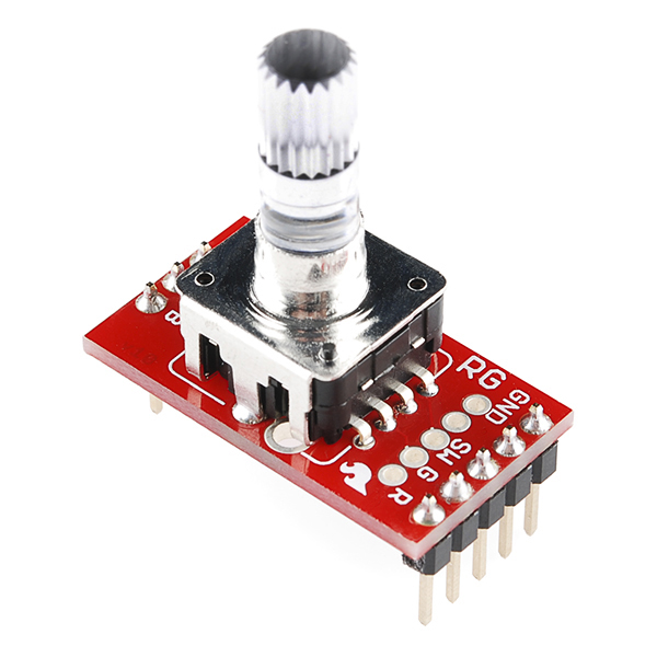
SparkFun Rotary Encoder Breakout - Illuminated (RG/RGB)
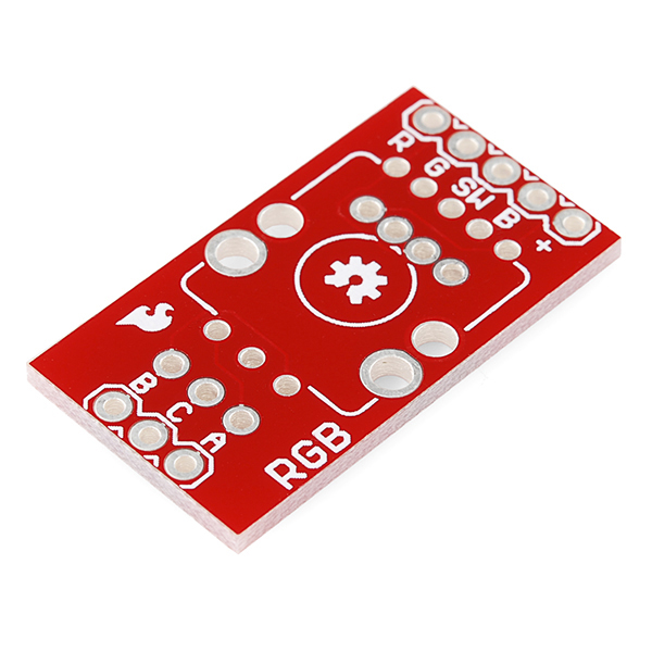
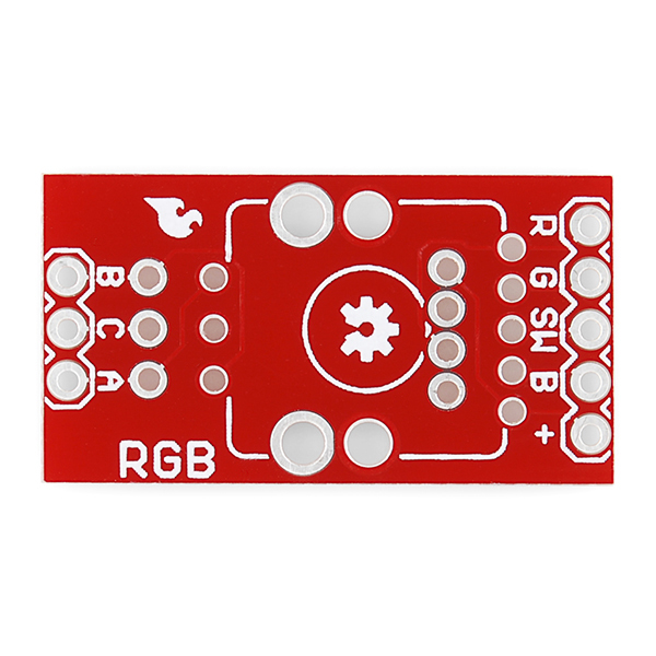
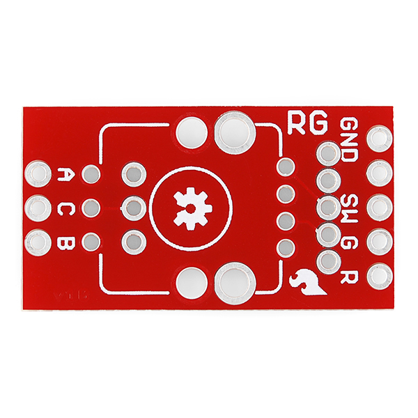
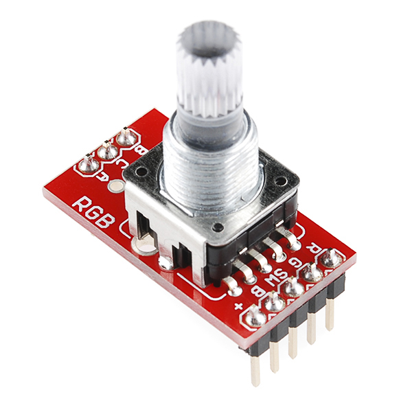
This is a clever little breakout board for both the RGB and R/G illuminated rotary encoders. On one side, it breaks out all of the RGB pins to standard, breadboard friendly, 0.1" headers. Turn it over and it has a footprint for the R/G version! Simply solder an encoder down to the board and you're ready to add illuminated input to your next project.
SparkFun Rotary Encoder Breakout - Illuminated (RG/RGB) Product Help and Resources
Core Skill: Soldering
This skill defines how difficult the soldering is on a particular product. It might be a couple simple solder joints, or require special reflow tools.
Skill Level: Rookie - The number of pins increases, and you will have to determine polarity of components and some of the components might be a bit trickier or close together. You might need solder wick or flux.
See all skill levels
Comments
Looking for answers to technical questions?
We welcome your comments and suggestions below. However, if you are looking for solutions to technical questions please see our Technical Assistance page.
Customer Reviews
4 out of 5
Based on 2 ratings:
If you are buying an Illuminated Rotary Encoder, you probably want this
This little board makes it a lot easier to use the Illuminated Rotary Encoders (both RG or RGB). I have the RG which I bought without this board -- that was a mistake. I am sure I could have soldered a bunch or wires to each pin, then tried to keep track of which wire did what. But who wants to do that? The Illuminated Rotary Encoders will not fit into a breadboard, but adding headers to this breakout will -- mostly.
If you do plan on butting this on a breadboard, be warned that the two rows of headers you attach will be a bit far apart. They will fit on a breadboard (e.g. columns a and i) but access to some of the other breadboard holes in those rows will therefore be a bit hampered. You'll either have to connect some of the other wires to the breadboard (and have them lie flat) and then inset the breakout board over them, or have the breakout board span two breadboards.
I have one suggestion (for Sparkfun). At present, these are not mentioned in the description section of the Illuminated Rotary Encoders. That would be helpful -- for my anyway. They are listed in the Hookup Accessories, but there are often items there that seem like they should be in the Similar Items section and therefore can be easily glossed over.
Too long for a standard breadboard, otherwise fine.
It does what it's supposed to do and it works fine, BUT: If you put it on a standard breadboard, there is no way to have both sets of rows accessible at all, because it goes from the outermost pin on one side to the second-outermost on the other side. If it were even one pin length shorter, it would be a ton easier to use. I just went and made my own (just for the RGB types) that goes from the middle pins in each set of rows, so about 0.3" shorter. So it's nice, but be aware that you'll need a way to set up two breadboards, or otherwise get something larger to work on to actually use both sets of headers at once. I think that's a side-effect of needing to support both of the RG/RGB pinouts.
Can I use this encoder with this board?
can I use this breakout to mount a rotary encoder with momentary switch?
I note the two different positions for the encoder that delivers a 3&4 pin or a 3&5 pin configuration. what I need is a 3&2 pin configuration that looks like it can work on the 3&5 layout.
I want to use the encoder to scroll a menu on an LCD and the press to select it.
Is there a simple schematic i can use to wire this to an arduino. I will be using the encoder is was designed for.
It depends on the color rotary encoder you are using. The RGB uses a different pinout than the RG. At a minimum, I did add some comments for each respective code if you are using an ATmega328P-based Arduino. Just keep in mind the RGB requires a pull DOWN resistor while the RG requires a pull UP resistor.
This is a great board for the RGB encoder. It makes it very easy to make all of the connections to the encoder. In addition, I found another non-advertised feature with this board.
After the RGB encoder and the three leads (A, C, B) are connected there are three holes still open just above where the three wires are soldered into the board. I was able to insert .01 mfd capacitors between A and C and B and C and solder them into the board. These capacitors suppress the wiping noise that can occur when rotating the encoder. I discovered the noise with an oscilloscope while trying to determine why I was getting erratic counting of encoder pulses while testing several different sketches from the Arduino Playground.
Some of the sketches were software de-bouncing the switches, but even that was not 100% effective. After I installed the two capacitors the encoder works flawlessly. Therefore if you are having problems getting encoders to count without errors adding two small bypass capacitors: one between (B to C ) and the other between (A to C) should resolve your issue. After I installed the capacitors, I did not observe any noise on the oscilloscope trace.
Just a thought: if you wind up doing another rev of this board, it might be worth including through-hole footprints for debouncing caps on the A and B terminals, in case the user would like to add them. From the .brd file it looks like you could fit a CAP-PTH-SMALL package on each side of JP1.
Do you need to use resistors for the LEDs
For most applications: yes, you'd want to pick resistors based on the driving voltage - there are no resistors on the board itself. If you need to know what resistor to use, find the forward voltage and current ratings for the LEDs in the appropriate encoder's datasheet, and hit it with some math (or online LED resistor calculator).
This is a handy board, but why is it dual purpose? It's either going to be soldered to an RG or an RGB encoder, but never both. Why not make two specific purpose BOBs? They could be smaller, cheaper, fit in a breadboard easier, and only have one set of labels (I keep getting myself confused as to whether I should read the labels on the top of the board or the bottom).
File this under "you can't please everyone." While the pins now line up, the board is too wide for an average sized breadboard (5+5 pins) -- it covers 9 of the 10 pin rows.
Heh, this is true. The 3-4 rows under the breakout board should still be usable though. It requires a little planning ahead - wiring before you lay the board down - but it's not too painful.
Are the breakouts on either side of the board still not lined up? I had some of the RG breakouts, and it was a little irritating that the pins were not lined up so it can't sit in a breadboard straight.
Sorry about the last board! This time all of the holes line up, and the board is breadboard compatible.
You are right that this board fits on a breadboard. However, it is too long, so that only one side (either [GND, SW, R, R] OR [A C B]) can be connected using jumper wires next to the breakout board. So, unfortunately it is useless on a breadboard.
The rows under the breakout board should still be usable, though. Just have to plan ahead, and lay some wires down before plugging the board in.
This would work I guess, but I consider it not very user friendly. For a next revision I propose to place the breakout pins to the left and right (not top and bottom) of the breakout board. Then it can be used in "landscape" orientation and jumper wires can be easily used.
The breakout board for the rotary encoder RG is better in this sense (jumper wires can be used on both sides), except that the breakout pins are not properly lined up.