- Home
- Product Categories
- Connector Boards
- SparkFun RS232 Shifter SMD (No DB9)

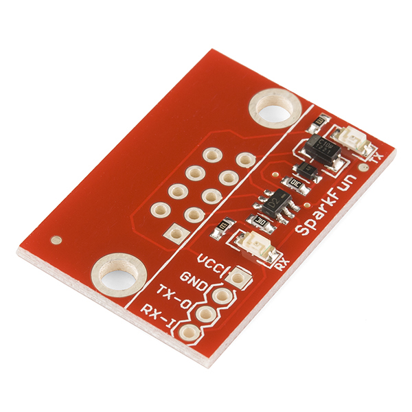
SparkFun RS232 Shifter SMD (No DB9)
The smallest and easiest to use serial conversion circuit on the market! This board has one purpose in life - to convert RS232 to TTL and vice versa (TX and RX). This will allow a microcontroller to communicate with a computer. Shifter SMD is powered from the target application and can run at any voltage! That's right - power the board at 5V and the unit will convert RS232 to 5V TTL. Power the board at 2.8V and the Shifter board will convert RS232 to 2.8V CMOS TTL. Includes two indicator LEDs for TX and RX. Runs from 300bps up to 115200bps.
This version comes with no DB9 connector attached. Useful for field installations and projects where RS232 serial is coming from something other than a DB9 cable.
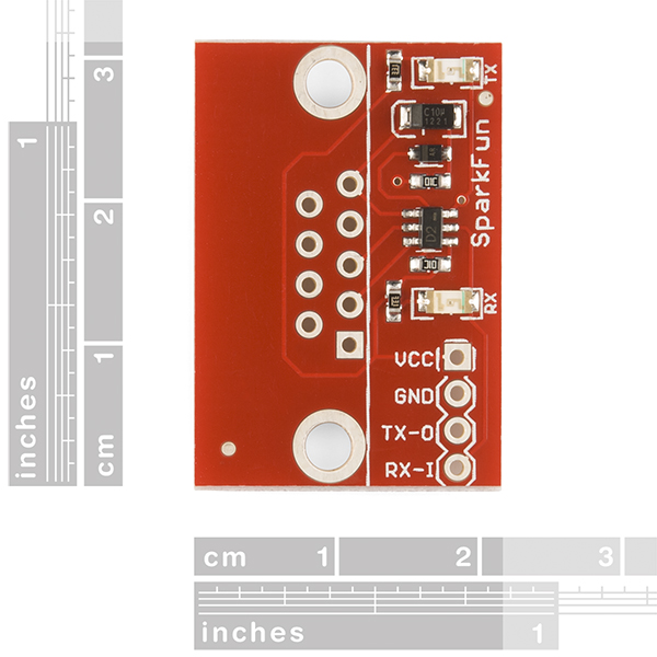
- 1.2x1.1"
SparkFun RS232 Shifter SMD (No DB9) Product Help and Resources
RS232 vs TTL Serial Communication
For more information about RS232 and TTL serial, try looking at our tutorial here => [ https://www.sparkfun.com/tutorials/215 ].
Lower Voltage
We tried converting RS232 voltage down to 1.8V but it was not able to work. The lowest seemed to be around 2.1V with the RS232 Shifter. We recommend using the RS232 Shifter running at 5V (or anything higher than 2.8V) for the TTL side and further convert the signal down to 1.8V with the TXB0104 [ https://www.sparkfun.com/products/11771 ]. The TXB0104 can translate down to 1.2V. Make sure that you have 5V and 1.8V to set the logic levels with each respective TTL side.
Core Skill: Soldering
This skill defines how difficult the soldering is on a particular product. It might be a couple simple solder joints, or require special reflow tools.
Skill Level: Noob - Some basic soldering is required, but it is limited to a just a few pins, basic through-hole soldering, and couple (if any) polarized components. A basic soldering iron is all you should need.
See all skill levels
Core Skill: Electrical Prototyping
If it requires power, you need to know how much, what all the pins do, and how to hook it up. You may need to reference datasheets, schematics, and know the ins and outs of electronics.
Skill Level: Noob - You don't need to reference a datasheet, but you will need to know basic power requirements.
See all skill levels
Comments
Looking for answers to technical questions?
We welcome your comments and suggestions below. However, if you are looking for solutions to technical questions please see our Technical Assistance page.
Customer Reviews
3.5 out of 5
Based on 10 ratings:
2 of 2 found this helpful:
Shifter didn't work for transmitting (for me)
I could receive using this board (after realizing I needed a null modem), but couldn't send signals properly. I ended up getting a MAX232 which is working perfectly -- should have gone that route all along for my project.
1 of 1 found this helpful:
Worked fine for both RX & TX for me
I have this device installed in a Motorola Micom Mobat 2ET radio, along with the Bluetooth Mate Silver WRL-12576, and the wireless serial connection is fantastic. Bidirectional data transfer is fully functional.
What may not be clear to someone who cannot read a schematic, and understand the circuit, is that the TX-0 on this board connects to the RXD on the serial device while the RX-1 on this board connects to the TXD on the serial device. When properly connected, this functions perfectly.
1 of 1 found this helpful:
Works great, once you figure out how to hook it up!
I was powering this with VCC=5v and wondering why the TX-O wasn't producing a signal on the RS232 side.. while my MCU can accept 5V signals, it only produces 3.3v logic level outputs.
Switched the VCC to 3v3 and everything is working perfectly!
1 of 1 found this helpful:
Doesn't work for me
I'm hooking this up to a RPi3 in order to communicate with an RS232 device. On the RPi, I connected the 3.3V to Vcc, GND, UART0 TXD to TX-0 and UART0 RXD to RX-1. When sending from the RPi, the TX LED blinks, but the signal coming out on the DB9 RXD pin is only the leading edge of each bit and is only about 100mV in amplitude.
I tried to connect the DB9 RXD to TXD and read off the RX-I pin, but nothing comes across. Sadly, it appears this device does not work as advertised.
Hello!
You can reach out to our technical support department here: https://www.sparkfun.com/technical_assistance I am sure they would be happy to assist you to the best of their abilities.
1 of 1 found this helpful:
Lights respond but no RS232 signal
I'm using one of the bi-directional logic converters (BOB-12009) - the lights come on for both RX & TX but no signal on the RS232 transmit when my processor sends a signal. All I can figure is the logic converter doesn't have enough power. I spent about $50 on 5 of 'em - can't get any to work. Used brand new converter and separate new power supply. Must be a bad batch.
1 of 1 found this helpful:
Worthless
Look at the schematic before you buy this. The circuit doesn't do proper voltage conversion, it's just unreliable hack built with a couple transistors. I would strongly recommend buying the MAX3232 isntead.
No documentation!!!
NO DOCUMENTATION ANYWHERE. A very simplified circuit schematic is not what I would consider documentation.
I did eventually get it to work, but with far more difficulty than necessary. Hint: try switching the Rx and Tx lines on both the RS 232 and TTL sides, and try all combinations. Also, try assuming the pins 1-5 are swapped (5-1), as it is hard to tell which side of the board is up. But it works!!
@3.3V will not transmit
Got it to work for receiving, but not transmitting. Also if using as a DTE (with male plug) then labelling on board is useless / wrong. My device is a DTE and is receiving from a DCE. had to swap pins 2, 3, as well as the TX and RX lines on the TTL side. That worked. However my other device which is a DCE, and meant to transmit to a computer. Scope shows data on the TTL TX pin, but nothing on pin 3.
Worked perfectly
Neat little design, worked perfectly the first time I used it. As other reviewers have said, the TX and RX pins are from the perspective of the RS232 device, not the UART device.
"...can run at any voltage!"
challenge accepted. My friend has a tesla coil.
I have a wifi MCU on one end and a Picaxe on the other. Trying to send ttl from wifi mcu to picaxe rs232 wired TX from wifi MCU to RX on shifter and wired RX on rs232 side to Picaxe. The TX lights on the MCU and the RX lights on the shifter but nothing is happening on the Picaxe. It should be lighting an LED. I have switched the wires every way I can think of and still nothing!
Probably too late, or maybe you've figured it out already, but make sure you power this shifter with VCC matching the logic level arriving in TX-O. I had this same problem (TX LED flashes but no RS232 TX signal) with VCC=5V, and using the correct input voltage VCC=3V3 ensures proper RS232 TX operation.
Without knowing more about the wifi MCI its impossible to say. Email techsupport@sparkfun.com with more information and they should be able to help. Also, make sure that the picaxe is rs232, I'm pretty sure its ttl like most microcontorllers.
Could two these be used with two of the XTend 900 1W RPSMA - 40 Mile Range to facilitate two way communication of an rs-232 setup. I don't think sparkfun sells the interface boards made by Digi International that would take care of the logic level conversions. Thanks!
TX-O on this goes to Arduino's RX RX-I on this goes to Arduino's TX
To solder this one to a Female DB9 cable: - The square pin marks Pin 1 of the cable. Most cables have pin numbers etched on the from of the connector. If yours doesn't have these markings, put the female connector behind the PCB, so the pins align. This way you can see that Pin #1 is on the upper right. To get to Pin #9 count counter-clockwise.
For those looking at this for their BeagleBone Black; I can verify that this board works quite well at the 115200 baud rate used for that system. Since I have a native EIA-232 port on my mobo, I picked up one of these with a PRT-00429 and I haven't looked back. Just make sure to pick up a true pass-through DB-9 cable if you go this route.
I'd like to connect a serial device that has a female plug (much like a Weather Underground station) to my Arduino. The Arduino just needs to receive data (a short burst of ASCII every minute at 9600 baud); it doesn't need to transmit. I guess I want my Arduino to be a DTE, not a DCE?
There's no male version of the DB9 component (like PRT-00429) sold to go with this board. So ... can I get a ribbon cable instead, with the DB9 connector (PRT-11156), and just solder the leads directly to this board? Which pins should I solder to which holes? Or, is this overkill, and all I need to do is make a voltage divider to step the 12v from the device down to 5v?
Just struggled with this for several days--if the serial device has the DB-9 plug, then it's at RS-232 level. That makes it the computer (DTE) for the purpose of this shifter. The Arduino/Netduino at TTL level is the modem (DCE). Or, I've completely lost my mind, which is quite possible at this point.
OK, may be a silly question, but the board seems to have white paint around the pin contacts where I'd expect to see copper. Do I just ignore it and solder as normal? It vapourises??
That's actually tinned copper. It reflects rather brightly in our studio, but it's silver in real life and very easy to solder to.
I would like to see a smaller version of this board. Just have the needed pins for the DB-9. Makes it more embeddable.
I play with devices that put out RS-232, but DB-9 is an option. So a small rs-232/ttl converter would be great.
I just spent several days trying to figure out a problem with a data communication project. It was traced back to this level converter. As mentioned/quoted by Paradoxial this type of "voltage stealing" converter may not work particularly well in all situations. Using a "real" level converter (using something like a Maxim 232 chip) might be a safer bet.
I love Sparkfun products, but this is one I can't fully recommend. It worked OK on an Arduino but not on other projects.
Ok, so how does sending a transmission of a TTL get magically "boosted" up to +-12Volts RS232 on the other side when the only power supply is the TTL voltage?
A quotation from the other shifter comment page: