
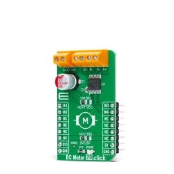
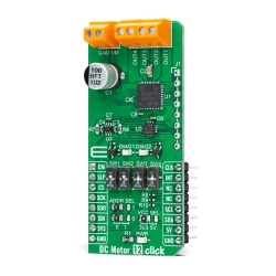
MIKROE DC Motor 12 Click
DC Motor 12 Click is a compact add-on board with a brushed DC motor driver.
Product Overview
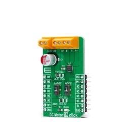
DC Motor 12 Click is a compact add-on board with a brushed DC motor driver. This board features the TB9054FTG, a PWM-type, dual-channel, H-bridge, brushed DC motor driver from Toshiba Semiconductor. The TB9054FTG is rated for an operating voltage range from 4.5V to 28V, with the motor controlled directly through a PWM signal or SPI serial interface. In addition, this driver allows a dual configuration with two motors with 5A current ratings per channel or one 10A channel drive in a Parallel mode of operation. It also has complete diagnostic and protection capabilities supporting robust and reliable operation. This Click board™ is suitable for driving DC brushed motors in various automotive applications such as control of the throttle valve, engine valves, retractable door mirrors, and seat heater.
DC Motor 12 Click is based on the TB9054FTG, a dual-channel, H-bridge, brushed DC motor driver from Toshiba Semiconductor. The TB9054FTG allows a dual configuration with two motors with 5A current ratings per channel or one 10A channel drive in a Parallel mode of operation. It is also rated for an operating voltage range from 4.5V to 28V, with the motor controlled directly through an SPI serial interface or PWM signal from an unpopulated header. The PWM control with low on-resistance enables highly efficient motor drive output, ensuring reliable operation for highly competitive automotive applications.
Besides the SPI communication, several GPIO pins connected to the mikroBUS™ socket pins are also used to control the TB9054FTG associated with the PCA9538A I2C-configurable port expander, such as Sleep Mode pin and DC motor channels current monitor routed to the RST and AN pins (SLP and CM) of the mikroBUS™ socket. The PCA9538A also allows choosing the least significant bit (LSB) of its I2C peripheral address by positioning SMD jumpers labeled as ADDR SEL to an appropriate position marked as 0 and 1, alongside its interrupt feature routed to the INT pin of the mikroBUS™ socket.
As mentioned, this Click board™ supports double or single DC motor configuration. To select the motor control and operational modes, the corresponding switches on the board marked with SW1-SW4 are used. The first two represent the switches for motor control selection - more precisely, the choice of control directly by the PWM signal or through the SPI interface - while the second two represent the selection of the motor operational mode. There are four possible modes, i.e., Small Mode (two separated channels), Large Mode (two channels are connected and support one DC motor), Half Mode, and Prohibited Mode, where the channels are completely disabled.
The control and PWM signals can also be brought externally via the onboard header J1. In that case, the PWM1 and PWM2 pins specify forward, reverse, or brake modes for motor 1, and the PWM3 and PWM4 pins specify these modes for motor 2. The enable EN pins select the drive or stop mode for the motor. A broad range of configuration options for this driver, control, and mode selections, can be found in the attached datasheet. This Click board™ also has additional LEDs for anomaly indication. Suppose a state such as an overtemperature or overcurrent/under voltage is detected. In that case, such anomaly is indicated by red LEDs marked as DIAG1 and DIAG2 associated with the interrupt pin.
The DC Motor 12 supports an external power supply for the TB9054FTG, which can be connected to the input terminal labeled as VM and should be within the range of 4.5V to 28V, while the DC motor coils can be connected to the terminals labeled from OUT1 up to OUT4.
This Click board™ can operate on both 3.3V and 5V logic voltage levels selected via the VCC SEL jumper. Therefore, both 3.3V and 5V capable MCUs to use the communication lines properly. The Click board™ comes equipped with a library containing easy-to-use functions and an example code that can be used, as a reference, for further development.

Features & Specs
- Interface: I2C, PWM, SPI
- Compatibility: mikroBUS™
- Dimensions: 57.15 x 25.4mm
- Input Voltage: 3.3V, 5V, External
- Supply Voltage: Min. 3.3V, Max. 5V
- External Supply Voltage: Min. 4.5V, Max. 28V
- Output Current: Min. 5A, Typ. 6.5A, Max. 10A
- Operating Temperature Range: Min. -40°C, Typ. +25°C, Max. +125°C
Customer Reviews
Stock and Customer Discounts
Available Discounts
- $21.80 | 25+ units
- $20.66 | 100+ units