- Home
- Product Categories
- EL
- SparkFun EL Sequencer

SparkFun EL Sequencer
We've heard you, and made a number of improvements to our EL Sequencer. The new version adds zero-crossing optoisolated triacs for noise-free operation and full isolation between the AC and DC sides, and includes a 1.5A adjustable linear regulator to supply regulated DC to an external inverter (not included).
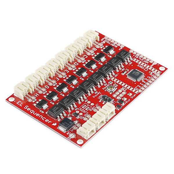
The SparkFun EL Sequencer is a board that contains an Arduino-compatible microcontroller, and circuitry for controlling up to eight strands of electroluminescent wire. EL wire is flexible plastic cord that glows brightly when high-voltage AC is applied to it. It's available in numerous colors (see the related products below), runs cool, and requires very little current, but can be difficult to work with because of the high-voltage requirements. The EL Sequencer can safely switch high-voltage AC on and off, allowing you to easily create animated displays or whatever else your imagination can come up with.
In addition to this board, you will need an inverter (a component that generates the high-voltage AC needed by EL wire), EL wire/tape/panels, and a 5V FTDI BOB or cable to load your own programs. The board also has headers for XBee and NRF24L01+ radio modules for wireless projects. SparkFun carries two inverters, a 3V-input version that can drive a few feet of EL wire, and a 12V-input version capable of driving dozens of feet of EL wire. Choose the one appropriate to your power source and driving requirements. See the tutorial below.
Nate has used EL wire to make amazing interactive costumes; check out his Heartbeat Straitjacket and demo video.
Note: The initial run of the board contains a silkscreen error; the FTDI "black" and "green" labels are reversed. If you're plugging an FTDI BOB into the board, it goes in right-side-up as you'd expect.
Replaces:COM-09203
- ATmega 328p running at 8MHz, with Arduino bootloader
- Eight opto-isolated, zero-crossing EL control channels
- Headers for XBee and NRF24L01+ for optional wireless control
- No library needed - control is as easy as turning a LED on and off
- Integrated 1.5A linear regulator (LM317) to supply regulated DC power to external inverter
- Linear regulator preset to 3.3V, but can be changed via PTH resistors, or bypassed entirely
- Can be powered by a 3.7V Lipo battery (using 3V inverter), or an external 3.3V to 16V supply (using 3V or 12V inverter)
- 5V FTDI BOB or cable required for reprogramming, not included
- External EL inverter required, not included
- Schematic
- Eagle files
- Example code
- Datasheet (MOC3063S)
- Datasheet (Z0103MN)
- Datasheet (LM317)
- Tutorial: setting up an EL system
- Jacob's Ladder Project
- GitHub
SparkFun EL Sequencer Product Help and Resources
Sound Reactive EL Wire Costume
December 31, 2015
Learn how to make your EL wire costumes sound reactive in this project tutorial.
EL Wire Light-Up Dog Harness
October 30, 2015
Learn how to create a light-up dog harness using EL wire for when you need to take your four-legged friend for a walk in the dark.
Core Skill: Soldering
This skill defines how difficult the soldering is on a particular product. It might be a couple simple solder joints, or require special reflow tools.
Skill Level: Rookie - The number of pins increases, and you will have to determine polarity of components and some of the components might be a bit trickier or close together. You might need solder wick or flux.
See all skill levels
Core Skill: Programming
If a board needs code or communicates somehow, you're going to need to know how to program or interface with it. The programming skill is all about communication and code.
Skill Level: Rookie - You will need a better fundamental understand of what code is, and how it works. You will be using beginner-level software and development tools like Arduino. You will be dealing directly with code, but numerous examples and libraries are available. Sensors or shields will communicate with serial or TTL.
See all skill levels
Core Skill: Electrical Prototyping
If it requires power, you need to know how much, what all the pins do, and how to hook it up. You may need to reference datasheets, schematics, and know the ins and outs of electronics.
Skill Level: Competent - You will be required to reference a datasheet or schematic to know how to use a component. Your knowledge of a datasheet will only require basic features like power requirements, pinouts, or communications type. Also, you may need a power supply that?s greater than 12V or more than 1A worth of current.
See all skill levels
Comments
Looking for answers to technical questions?
We welcome your comments and suggestions below. However, if you are looking for solutions to technical questions please see our Technical Assistance page.
Customer Reviews
4 out of 5
Based on 4 ratings:
1 of 1 found this helpful:
I was wary of this product and I still am
The documentation on this product isn't great about how often it can switch the outputs. I don't want to burn it out, but I'd also like my display to look a bit more impressive than just cycling the lights every second.
The documentation is also very clearly written for the Escuido Dos, and while it's almost directly applicable, there are a few differences and I found I was browsing both of the schematics to try to make a good guess of which setup would work and which wouldn't.
The default code is very simple, and works to test all the outputs, but I'm definitely going to need to reprogram the chip, and given I'm just making a light-show that's a bit disappointing.
The good news is that everything wrong with this board could be fixed with a website and default code update, so this could be easily improved.
I got it working with parts only from sparkfun: this board a 12V inverter (with a JST pigtail soldered in) a JST to barrel jack converter, a 12V DC Wall wart and EL wire
Hi, Sorry for the troubles. I will be posting your comments up into a revision review request. We're always trying to improve our documentation. Maybe we can get things cleaned up a bit to help future users avoid similar issues. Thanks for the feedback!
Good Arduino EL interface!
I used this board to turn on four 1M EL Tape strips in a coat closet. I used a 5 mV per gauss Allegro A1324 Hall Effect Sensor IC and a tiny magnet (COM-08644) in the door to sense door position and then progressively turn on more light the further the door opened. It works well. I did learn two things, PWM does not work well with EL and the EL inverters (COM-10469) burn out eventually (~36 months, I leave them on 24/7). I recommend the board, it makes projects like mine easy. I'd love to see a USB connector on this in the future.
Good Product, Not for beginners
Original Assessment: I've had a number of issues with my Sequencer. A code that worked great with a Mega and a EL Dos Escudo completely fried 4m of EL tape. Not sure what the issue is. I've repaired and retested wires only for the sequencer fry it again. No clue what happens. I'm reverting back to my Dos. I talked to tech support and although they were very responsive they didn't offer much of a solution besides changing inverters. It didn't solve my problem. I originally suspected it was some sort of Voltage issue because I originally used 12V and a 9V to power the board. It was a dumb mistake but I don't think permanent damage was done. However when I try to power up really more than 1 circuit it fries the wires. So long story short I had a pretty rough experience. The El Escudo Dos is much more reliable and safe in my opinion.
After more development and research: Like a real dummy, I did not pay much attention to my inverter selection. This is a bit due to the lack of options on adafruit and sparkfun. Both sites offer similar inverters. Here on sparkfun, they offer the 12V wall wart inverter, on adafruit the more module inverters are offered in 3V and 12V. Here's where everyone planning on using this device or has plans for a large scale EL Project main speaking with EL Tape and Panel needs to pay attention. THESE INVERTERS ONLY SUPPORT UP TO 100 cm^2. That means 1m of tape or 10cmX10cm of Panel. FOR ANYTHING GREATER CHECK THIS SITE FOR HEAVY DUTY INVERTERS: www.thatscoolwire.com. I used the Powerhouse inverter to light up over 700cm^2 of EL Panel and Wire without destroying it all. (For projects using EL Wire these sites offer great inverter and I promote their use.) NOTE: If you use the other inverters with more than the suggested amount you're playing a risky game. The inverter will start to experience voltage spikes and it will likely burn out all your EL product.
So more about the product, if you have done you research and have all the right equipment, this is an awesome product. That being said documentation and warnings like these are not as present as they should be. My best advice for this product: get the correct inverter, test slowly to protect your wires, once confident in your design go for the goal, the product can likely take it if you've done good research and have all the right components for your system.
I have bought the El sequencer and it's not working well. the main problem is i can't load any program. i alwais get this error message "avrdude: stk500_getsync(): not in sync: resp=0x00". I have read this error is because i have choose a wrong board option and i have tried with all the option given for atmega 328. How should i configure the arduino options of board and programer? any other sugestion? thanks a lot
Sorry about the problems! Here's the quick list of things to watch for:
I hope this helps, but if none of these solves your problem, contact our Tech Support Department who will definitely get you up and running.
I finally got this working and provide this updated post.
I have built a system that has one arduino uno / xbee S1 (master) that controls three el-sequencer boards with xbee S1. Bobby from sparkfun support was helpful.
It's true that the xbee must be removed each and every time you download to the arduino chip on the el-seq board. I am experimenting with their (bent pin) approach to bypass this to mosi/miso pin on the el-sequencer.
the original sketch was built on the doorbell program (button/bell) in the o'rielly book. that book tends to jump around and was hard for me to follow.
Networked arduinos - and espsecially wireless networked arduinos require more planning. My test lab had two arduino uno, two sparkfun shields, and two xbees. I later substituded one of the unos (receiver) for three el-sequencer boards.
To test the transmission and reception between two boards I used the standard serial libraries and hardwired (rx/tx) and (ground) between the two arduinos. This worked - so I knew the scripts were ok.
Get familiar with XCTU. Buy the sparkfund xbee usb board and leave an xbee running on a separate system to monitor the radio transmissions real time. It's also easier to manage firmware settings (DH/DL) in XCTU - and the monitor is split screen and shows the actual charachters next to an ascii conversion. the usb board can also be used with a standard "cool term" terminal program.
When i moved from three wires between the board to two xbee S2 the communication failed after 30 seconds. My test script sent a serial.write every 10 ms. Garbage on the screen
To fix this I had to do three things .
First off I had to downgrade to the xbee S1.
Second thing - I moved from arduino native serial libraries to < software.Serial.h> on the master (transmitter) which provides flow control but insists that you redirect away from physical pins 1,2.
//in the sketch you'll do this SoftwareSerial xbee(2,3); //Rx = 2 , Tx = 3
// and this in setup xbee.begin(9600);
// and instead of the serial.write xbee.write(foo);
This is an advantage because i no longer need to take the xbee S1 off of the sparkfun xbee shield. Just flip the switch from UART to DLINE. I only needed these newsoftserial libraries on the transmitting end. These libraries are included in version 1.0 and above of the arduino IDE.
Third thing - I had to get the correct router settings. The transmitter needed to be set like this. (Radio a transmit) DH =0; DL=FFFF; MY=1. Each of the receiver - slaves needed to be like this: (Radio b,c,d receive) DH=0; DL=1: MY=2. Obviously you will need to set a unique PID for all four.
Finally - I moved the code off the uno to the EL-sequencer. Because pins 2-9 are hardwired to the el-wire pins i had to move some things around. And this also prohibits me from using <software.serial.h> so that i don't have to unplug the xbee each time.
I now have the master uno transmitting with delay(20) to three el-sequencers. On the sequencers I'm using a 12 battery to power the inverter - and also to power on-board arduino.
In the comments below, found by using chrome's Edit -> Find -> xbee ...
I believe the FTDI and XBEE headers share a couple of pins which causes problems when both are connected. Since you mentioned the serial console still displays data even though the XBEE fails, I assume you have both the FTDI and XBEE connected.. A post in the comments below says only to have one connected at a time.
When programming the EL Sequencer using the FTDI board, remove the XBee. When using the XBee, remove the FTDI board. Always use one OR the other.
I love this idea a ton. But, it would be a humongous help it under the description (AND the features - or at least one of the two) you put the size of the JST connectors that folks need and how many. are needed. You could put a link there to the product. This is important because some other EL providers (A-hem) use a different JST connector. About 6 months ago I bought some EL wire from someplace not to be named and then I saw both your Sequencer and the Escudo. I thought, "hey, I can just plug those EL wires in to the sequencer or escudo." No, I can't. They're not the same size. But, there's no way to know that from the description or features.
**using <softserial.h> on el-sequencer with the sparkfun xbee breakout board **
i've scratched my head over this for weeks and got a working solution. the xbee radio shares communications with the serial UART / serial console. This means that the xbee S1 radio has to be removed from its socket each time you download an arduino sketch.
While the sparkfun xbee shield allows for this with the DLINE switch by redirecting the xbee communication to pins 2,3 (see my post below) the el-sequencer reserves pin 2-9 for light channels A-H. And so the S1 radio with 20 tiny pins has to be extracted and replaced each time you download.
parts Here is the work around. You'll need to get the xbee breakout board (BOB-08276) and two of the 2mm xbee headers, as well as 8 tall .01" headers. Attach jumper wires from the xbee breakout board to the el-sequencer and leave the xbee off the shield until your final code rev. At that point you'll have to change a few lines of code to use the standard serial.
solder headers Build the xbee breakout board by soldering two 10 pin 2mm xbee headers to it. Solder some tall headers into 8 pin NRFL connection on the edge of the board near the FTDI. You'll need to solder the same tall headers to the 6 FTDI connectors.
If you have not noticed the other el-sequencer post, the FTDI is labeled backwards on early boards and you'll need to flip the black to green.
jumper from breakout to el-sequencer The Xbee S1 module will be on the breakoutboard - not the el-sequencer. Jumper from Xbee breakout 1 (vcc) to nrfl vcc. Jumper from Xbee breakout 10 (ground) to nrfl ground. Jumper from xbee (rx) breakout 2 to nrfl mosi which maps to D11. Jumper from Xbee (tx) breakout 3 to nrfl miso which maps to D12.
stop! before plugging the xbee S1 in get a volt meter out and check from pins 1-10 on the breakout board! check the polarity. you should get 3.2v dc
Within the arduino sketch
#include <SoftwareSerial.h>
// and then call the object xbee2:
hello i have a problem, 2 lines (output) They are always on, anyone knows what is wrong? maybe something was wrong, or maybe something is burned thank you...
Does anyone have any good ideas for housing the board, like a little plastic box?
Lego? Works well for lots of Raspberry Pi boards, though mine are in Pi tins.
Hey guys, I was wondering if it would be possible to use this unit to sequence 4 inch cold cathode lights, and if so, what sort of extra support electrickery I might need to provide. e.g. would your excellent 12 volt inverter be capable of driving said lights?
We've never tried it here, so caveat emptor. It's my understanding that CCFL tubes need a different inverter than EL, so I don't think our inverter will work. But, as far as the voltages and frequencies go, the board shouldn't have a problem with it, so connecting a CCFL inverter through the board to CCFL tubes should theoretically work (we've got the pigtails if you need them). If you try it, let us know what happens!
Yeah, I can use the inverter supplied with the tubes but I'd rather a more safely designed unit were available.
What I want to do is up the awesome in a Steampunk prop "raygun" I built that is essentially a (semi) portable set of case lights and a lumen disc in a fancy case (picture at http://colonelmoran.blogspot.com/2011/10/aetheric-neuralizer-in-action.html - the world's most incoherent build blog, so incomprehensible even I gave up on it eventually).
I had the idea to make a sort of "light screw" effect from El Wire for the barrel that would idle at one speed and get much livelier when the trigger was pulled or the stopcocks twirled, fairly screaming "Don't get in front of me" to the onlookers. Much fun would ensue (Steampunk stuff should at least look like it works in my opinion).
However, maddeningly, EL Wire is too dim to be worth the effort in this case, so I thought that maybe eight paired 4 inch green CC case lights could be induced to "rotate" about the barrel instead. Everyone knows Weird Science glows green.
The only problem with the supplied inverters is that I am certain that they somehow put an AC signal on the DC supply line. I came to this conclusion after getting a painful belt from the negative terminal of the 12 volt lead-acid accumulator I drive everything with during a test of the Steampunk raygun electronics, and by experimenting with carefully placed diodes which removed the problem.
Sparkfun would never sell me something that did that. Admittedly, one of the sequencers they did sell me puffed smoke for no good reason during a test but I fixed it with a bit of wire and some swear words and it's OK now. The other has given smokeless service whenever used, and has been declared "awesome" by several witnesses. If only the EL Wire were brighter.
there are three power connectors on the 11321. (AC in: DC out: Batt in) I've looked through the comments (no search ability for comments?) to find out how to work with the (DC out) connector to change it from /default/ 3.2 volt to 12 volts. The /limited/ product description says that there is a 1.5A adjustable linear regulator and I assume this is (DC out). How do i make the board work with the 12v inveter (COM-10469)
There's a solder pad just above the "AC IN" jst port, labeled SJ1 . Solder that. Now 12v will go to the DC OUT to the inverter.
Have you actually made this work? The idea of running the extra line in (at 12v) and out (at 12v - back to inverter) is so that the board can shut on and off the invertor and not burn it out. that's what i recall.
the schematic also allows that input voltage can be passed directly to invertor by closing SJ1 but warns that the inverter will see 5V with FTDI if power switched to USB. I guess this means that one should provide 12V to the middle input for board and leave the switch away from USB.
Still unclear if the board will switch the inverter on and off; and whether or not this is needed to prevent blowing out the inverter because there is no load.
ijustwanttoorder is correct. The big regulator is there to allow someone to run our 3V inverter with a larger VIN (5V or 12V) without damaging it. If you want to use our 12V inverter, you should power your system with 12V, and close solder jumper SJ1. This will send the input voltage (12V) directly to the inverter. The board does not have the capability to turn the inverter on and off.
Hi, i just bought some El Sequencers to light up dance customes... I bought some 12V(the biggest one) inverters from sparkfun too. In the description for the inverter it says it can drive 10-15m... but my customes will have like 30m of el wire. What can i do to light up all this 30m?
Are you going to power all 30M of EL Wire at the same time? If not the 10-15M inverter should be fine. If you are going to power all 30M at once you will want to use a different driver. I've powered 30M from a 10-15m inverter, the wire just didn't glow as brightly.
Yes, im gonna power all 30M at the same time. What did you use for this? Any recomendation?
Have you tested the current inverter with the length you want to power? Overdriving does shorten the life of the inverter so it's not an ideal solution. Sparkfun doesn't seem to have any inverters for longer lengths. The one place I've ordered from before has several. thatscoolwire. com and http://www.coolight.com/category-s/29.htm
i'm trying to do the same thing - using xbee wireless for synchronized el-wire on costumes. so far sparkfun support has not helped me with that request so i will probably return everything. i have asked for an RMA but they have not given to me.
one thing to do would be to use two boards - maybe someone else has a link to another vendor.
Why is it their job to do the work for you?
good day! could you inform what type ( some markings) connectors for EL Sequencer? where I can clarify the drawing or a technical description this connector ?
Our EL products use a 2mm, 2-pin JST connector. We offer pigtails with this connector that you can easily splice onto your own EL wire/tape/panels. You could also get the parts to build these connectors at Digi-Key, but you would have to crimp the pins yourself which is not easy.
Hello everyone. I am from Venezuela and I want to present as a suit project (like the boys team illuminate) to dance.
I read that ElWire is right, but I require this component and others, unknown to me, some could help me identify what are the materials I need to make the costume.
I know programming and me is very simple, but this brings some software component for development ?.
Any other information considered can help to make the purchase of the correct components are grateful, as I buy them and then send them to bring Venezuela, if there is no room for mistakes when buying.
thank you for all LGIG
Send an email to techsupport@sparkfun with a bit more detail as to what your costumes will look like. They'll help you pull together a full list of parts that you'll need. Good luck with your project!
What light patterns are preprogrammed on the board?
The test program that comes with the board just cycles through all the outputs and repeats. Normally you'll write your own light pattern programs using Arduino, which is very easy to learn.
Been working with one for a few days. Then all of the sudden it is caught in some sort of death spiral of resetting. I have a sj1 closed 12v setup. 12v going to battery in. The sequencer starts up runs for about 1 second correctly doing serial reports and everything. Then stat blinks, power blinks and it follows what looks like a reset. But right away does it again. It speeds up this cycle to a point where only the pwr light is blinking stat doesn't even come on. It does this on 12V battery or on a 12V power supply. If I switch it over to USB power. The chipset runs fine. I can switch the power over on the inverter and it works. But I designed this to be battery powered system and now it isn't working that way. Any ideas?
---update---
I have a workaround for today. I figure this may be a low voltage problem and I won't be able to find or fix the cause. Someone answer me this Is the 12V sending 3.3V and the USB sending 5V since sj1 is closed? How could I test that with a volt meter?
My workaround is adding a second 5V battery pack. But I would like to run it off of a single 12V gel cell.
Thanks for any ideas.
hey buddy, this problem bother me for a year!! easy to to solve. the regulator over heat, it resets vy quickly. use 3.7v to 5v battery for the arduino chip is perfect. use 2nd 12v battery for inverter. that's my solution for now.
it just doesn't work well with only one 12v battery for both inverter and the chip(reset all the time)
Can the El sequncer be controlled by vixen software ?
Hey Guys I am working on a Project . Me and my friends bought about 40 el sequencers and 42 xbees .. We need somebody who can Help us working with them .. how to hook everything together and help us with the programming
I just got my first EL Sequencer and wired it up to inverter, EL wire, and a 5V power supply and it runs the program that was loaded and the EL wires light. I seem to have bought the wrong version of the FTDI. I did not know there are two versions and I got the 3.3 volt version. I hooked it up to the EL Sequencer and my PC with and without the EL Sequencer powered and cannot get my computer to recognize it. I tried to modify the traces on the back of the FTDI for 5 volts but still get the same thing. Questions:
1 - Do I need to power the EL Sequencer off a separate power supply when connected to the FTDI and computer via USB to program? 2 - Could I have cooked my FTDI (and/or EL Sequencer) since I started with the wrong FTDI.
I experienced a weird comportment in serial communication, both wireless and cabled. If I set same baud rate in el sequencer and in the computer, odd characters are showed, typical of different communication speeds. In order to get correct communication I have to double baud rate on the computer side compared to el sequencer side. Have you some explanation?
You'll see this behavior when your code is compiled for a 16MHz processor but running on an 8MHz processor (it's running half as fast as it should be). When you're programming it, specify the board to be an "Arduino Pro or Pro Mini (3.3V 8MHz) w/ ATmega 328". If that doesn't fix it, let us know.
Thank you for the answer, now It works fine. I was confused because of 5V fdti, so I chose 5V processor, that runs at 16 MHz.
I am using the latest version el sequencer: COM-11323 and I believe I need to jump solder SJ1. I see a SJ2 and some A and B (located above DC Out / Batt In), but no SJ1. I am using your 12V Inverter modified so that DC input pluged into the "DC TO INVERTER" connector and the AC output into the "AC FROM INVERTER" connector as instructed, And a 12V power supply plugged to "Batt In". Do I still need to "jump solder SJ1" as is mentioned for other/older versions? How?
SJ1 is the large round jumper located right below the "AC in" label. If you're using a 12V supply, and a 12V inverter, then yes you should close that jumper. Let us know if you have other questions!
Hey! First of all, nice product! I really like the Sequencer. But this problem started recently: I've got a FTDI Basic to program my Sequencers. One of them is giving me the following error when trying to upload a program:
avrdude: verification error, first mismatch at byte 0x0000 0x0c != 0xff avrdude: verification error; content mismatch
the green led is blinking about every second when powered on. my other two sequencers are working fine.
Thanks in advance Toby
If the same computer/cable/FTDI can program the other boards successfully, there's probably a hardware fault on the wonky board. Contact our Tech Support Department, and they'll be happy to help get you back up and running.
hi which program i can use for programming this board , on this board i have to connect or make installation from usb cable to connect my computer!!!!
You can use the Arduino IDE to write programs for this board.
You will need a 5V FTDI Basic and a USB cable.
To connect the FTDI to the EL Sequencer, you will need to solder some header pins to it.
The tutorial linked above has more information on programming the board. Have fun!
I think I know what the error but I don't know how to fix it. Because I'm using a Mac, in Tool/Serial port I should be able to see something like /dev/tty.usbmodemfa131 which I don't see when I connect the FTDI basic and EL sequencer to my computer.
Any help will be greatly appreciated
Thanks
I'd start with the FTDI board by itself. If you have the drivers installed correctly, it should create a new TTY port when you plug it in, and if you talk to that port the LED on the FTDI will blink. Get that working before you try programming anything. www.ftdichip.com may help, as will Googling. If all else fails, you may have a bad board (it's rare but does happen), and you can contact us for an exchange. Good luck!
Hi!
I've been trying to upload the code to my sequencer and for some reason I get this error avrdude: stk500_recv() programmer is not responding. Has anyone gotten the same error? I'm using a FTDI Basic Breakout -5V and the EL sequencer. I can see the power and the stat light on. I went to Tool/Board and selected the arduino pro or pro mini (3.3 v, 8MHz) w/ Atmega 328. I'm also aware of the silk error on the board. I was thinking that It could be the programmer (I'musing AVRISP mkll) or the port (I'm using a mac to program).
Any help will be appreciated Thanks
Just a note to prevent future newbies (like me) from pulling their hair out. Check the card's power source switch if you start getting "avrdude: stk500_getsync(): not in sync: .." errors on upload. Mine came from the factory set to "batt" and I didn't think to check. D'oh!
would you please provide arduino example codes for blinking and qwerty keyboard control for example : "D" makes the 8 out puts light "T" makes channel one blink "S" makes them turn off
Here’s a quick example sketch that listens for the “QWERTY..” keyboard keys to turn a channel on, and “ASDFGH…” keys to turn a channel off.
this is somehow uselfull' but it doesn't satisfy me completely ... it listens for "QWERTY" to turn on and off separate channels i need to add "U" to turn all the channels at the same time and and "I" to turn them all off and "C" to make the 8 outputs blink it is urgent please
Check out the tutorial above on setting up an EL system for example code for blinking the lights. For QWERTY keyboard control, you can either do that using Serial communication with the Arduino hooked up over USB to your computer or get a USB Host shield to hook a keyboard into your Arduino directly for control.
how can i make el sequencer with arduino codes and how can i attach xbee chip for wireless control... should i soulder the pins in th square dots on the el sequencer and then attach the xbee ?
To program the EL Sequencer with Arduino:
To connect an XBee to the EL Sequencer:
If you have any problems or questions, contact our Technical Support department. Have fun!
Hi! I'm trying to use the Firmatta lib to communicate with a Processing sketch via serial, with no success. Does anybody know what do I have to do? Here is my Processing sketch:
import processing.serial.*; import cc.arduino.*;
Arduino arduino;
void setup() {
arduino = new Arduino(this, Arduino.list()[0], 57600); arduino.pinMode(4, Arduino.OUTPUT); }
void draw() { arduino.digitalWrite(4, Arduino.HIGH); delay(1000); arduino.digitalWrite(4, Arduino.LOW); delay(1000); }
I've tried to use the serial port to control the EL wire, with no success.. The example code / blink code works perfectly. . This is my "serial port code":
int incoming; void setup() { Serial.begin(9600); pinMode(4,OUTPUT); }
void loop() { if (Serial.available()) { incoming = Serial.read();
} }
Try this sketch which works for me. (It turns your keyboard into kind of a piano: 'q' will turn channel 2 on, 'a' will turn channel 2 off, etc.)
Hi thanks for your reply, but it's not working... Also, it's printing some very strange characters... When I try I reaaally simple code it also print very strange characters.. For exemple, this code prints " ~ ~ "..
int value = 0;
void setup() { Serial.begin(9600); Serial.println(value, DEC); }
void loop() { }
I've tried the same code ina Duemilenove & Uno, it works perfectly =((
Are you sure the serial monitor or terminal program is set to 9600 baud to match the Sequencer?
Are you using a 5V FTDI on the EL Sequencer? (A 3.3V FTDI won't work.)
Note that there's a silkscreen error on the EL Sequencer: the GRN and BLK labels are reversed. Is the FTDI board plugged in so the "BLK" label is closest to the corner of the EL Sequencer?
Do you have an XBee plugged into the EL Sequencer? Remove it while using the FTDI port as they both use the same serial lines and will interfere with each other.
Feel free to contact our technical support department, that can give you more hands-on assistance.
I 'vesolved the problem using another arduino to communicate via serial with the processing. Then, I've connected the arduino digital pins to the el sequencer analog pins. When the analogRead reads > 500 { turns on el wire } else { turns off }.. It works perfectlly
https://www.youtube.com/watch?v=ZVQMsMnOVh0
Is it possible to run this sequncer with an 11,7V Lipo and the 12 V inverter?
Yes, that should work very well. Close solder jumper SJ1 to send the battery voltage directly to the inverter. Have fun!
What would be a good enclosure for this board plus a 12v inverter? Are 3/8 nylon standoffs the way to go? Should I just feed the el wire tails in through a grommet or is there a better way? Do I need to worry about exposed terminals around a dry Christmas tree?
We don't have a huge number of enclosures, but you can see them here. Our big red enclosure might be overkill but it will definitely have enough room. Standoffs are good, but for a plastic box you can attach it directly to the box if you like. The EL strands are insulated, so you can pass them through holes in either a plastic or metal box, but grommets are recommended for a metal box. I wouldn't worry about EL causing problems with a Christmas tree; the voltage is low enough not to create sparking hazards. Do keep moisture away from the board (as for all electronics). Happy holidays, send us a picture when you're done!
Can I connect to the EL Sequencer EL Splitter Connector https://digitalmeans.co.uk/shop/image/cache/data/dfrobot/el_wire-splitter_connector-001-500x500.jpg control up to 32 El wire, Thanks!
I am new to programming with an FTDI BOB, what do I set 'board' to in my development environment?
Set your tools/board menu to “Arduino Pro or Pro Mini (3.3V 8MHz) w/ATmega 328”.
i sent an email to techsupport@sparkfun.com asking about some stuff since u told me to ask them there but it has been two weeks and no one replied me
Sorry about that! We've been closed due to flooding for the last several days, so that could be part of the delay. However, they may not have received your email (sometimes they do get bounced into the spam folder accidentally, so you might want to just send a quick follow up email. If they still don't respond, it may be worth calling.
Are there any other IO pins besides the 8 for EL wire sockets?
Yep - 4 digital/analog and 2 analog pins are available off the side of the board. They're not populated, so you'd want to get some headers. For further reference, see the schematic :)
Thanks a bunch, Kamiquasi! I wish I had the know how to tell from the schematic! I can only understand very basic ones, at this point.
No problem :) It definitely helps to be able to read schematics. I don't think this product would be the best 'intro to schematics', but let's give it a shot anyway.
If you open up the schematic (it's a PDF file), the main thing you'd want to look for (given the question) is the microcontroller itself. In most SparkFun cases, that means something PIC or something ATmega or ATtiny. Also in most cases, it'll be the block with the most pins (not always, but it can't hurt to scan for the big blocks first). In this case, it's the big block in the top right labeled ATMEGA328P.
On an ATmega, almost any pin other than the power/oscillator pins is some sort of IO pin, and in the block in the schematic all of them are presented on the right side (with power, oscillator, etc. on the left). If you look closely, you can see some of them labeled EL_A through EL_H.. those are the EL wire ones which we can't use, the same probably applies to the MISO, MOSI, RX, TX communication ones. There's also a whole bunch just labeled 'ADC_2' through 'ADC_7', though. Those look a bit more promising - but where do they go?
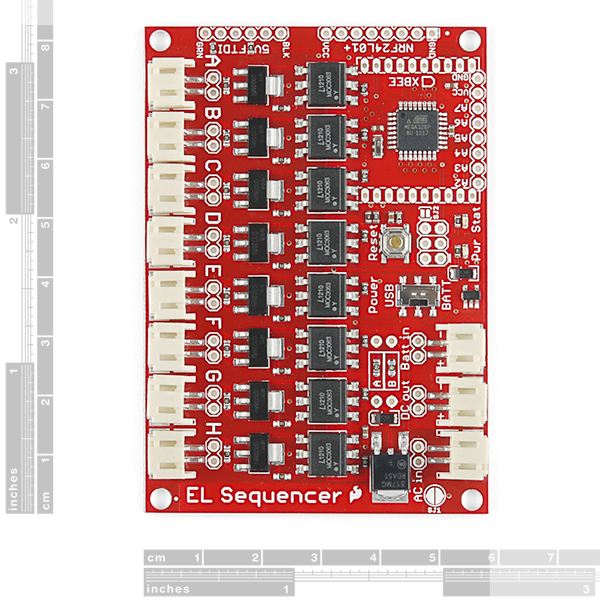
If you were to open the Eagle schematic file itself in Eagle, that would be pretty simple to answer, but without that it means just hunting the schematic drawing to see if those ADC_somethings appear somewhere else. Lo and behold, they appear again on the left side of the schematic, in the JP2 block. JP generally means some manner of connector or at least a breakout of pads. That JP2 block also tells you that power and ground connections should be in that same connector section. These pin names don't appear anywhere else, so that should mean that if you connect something to them, you wouldn't be interfering with anything else. Now to find them on the board, you'd generally look for that JP2 written somewhere in the silkscreen. SparkFun likes to leave those things out, though, but if you look at the image you can see a row of pins labeled A2 through A7 along with VCC and GND. Odds are pretty good that this row is JP2 in the schematic. Again, opening the file in Eagle would allow you to easily double-check that, but it's a pretty good bet just going off the schematic and images alone :)
( The schematic is also what notes the 2 pins as being analog input (presumably no output) only, in a little *footnote. That same information would be in the datasheet of the ATmega328p, but reading that behemoth is something else altogether. Note that this has some ramifications in terms of standard Arduino code - google "atmega328 adc6", without quotes, for a bunch of discussion and how-to's. Of course if you only need 4 i/o pins, you can ignore those two. )
I have a Sparkfun EL sequencer board, which uses the FTDI interface to connect to a USB cable. I would like to hook up a MakeyMakey via USB and communicate between the two. I have not had any success by hooking the two via a USB hub.
Is it possible to communicate between the FTDI/USB cable to another USB? Do I need to wire these together directly via USB? Are then even compatible?
Sorry, USB won't work that way on these boards. Both are set up to be peripherals connected to a larger computer. They don't know how to talk to other peripherals; it's a bit like connecting a mouse to a keyboard. Nobody's in charge.
You could certainly use the serial ports on both the EL Sequencer and the MaKey MaKey to talk to each other though. Connect TX on one side to RX on the other, and vice versa. Then you can send text from one to the other.
Did you close solder jumper SJ1 to allow the 12V supply to go directly to your inverter?
i am in a bad need for this if u could do a video it would be better because i dunno where to attach the pins and stuff like that
Email techsupport@ and they will be able to help you out further. Generally for detailed project instructions, we send people that way, as it's easier and faster for you to get help than using the comments section.
am sorry for the my questions am asking (i have a team of 8 we use el wires as suits and i need to control all of them from my computer using the xbee and sequencer ) please explain to me briefly how to do so including power sources and equipment i will need including arduino, chips, software.
have you finished your suits yet? i've done the el light suits already once.
no and i need help would u plzz contact me at martisparky@hotmail.com ??
how can i use xbee with el squencer ?
What if I wanted my pre-programmed light show on the El sequencer to begin after I sent the word "start" through the xbee?
is there is an el escudo dos shield ?
Yes!
how can i control el sequencer or el escudo dous in a wireless way ?
You can hook up a Bluetooth Mate plugged into the FTDI header on the Sequencer. For the Escudo Dos, it'd simply be a matter of hooking up a bluetooth or other wireless solution to the proper pins on your Arduino.
how can i control this sequencer in a wireless way and what is the difference between el sequencer and el escudo dous
The difference is that the Sequencer can be programmed itself, while the Escudo Dos needs to be hooked up to an Arduino board in order to run. See my response to your other comment in regards to the wireless control.
I read that running an EL inverter without a load attached can damage it. Does this board have some way to prevent that or does it assume one connection will always be on?
We've heard that as well and tried to kill our inverters (12V and 3V) by running them dry for extended periods, but they seem to handle it just fine. If you're using a different inverter with the EL Sequencer, you may need to consider this. Note that there's nothing on the board itself that prevents this from happening, so you'll need to handle this in your code (never let all the channels be turned off at the same time) if your inverter requires this.
I uploaded the example code but when I tried to write them all high it just kept performing the example code even though it says it uploaded the code right
That really shouldn't happen. Take a close look at your code to make sure it's doing what you think it's doing, that it's getting to the correct Arduino if you have more than one connected, etc.
all i did was put a comment tag before the line that turns the el back off in the example code
I just tried it and it works as you'd expect (the status LED will keep blinking, but the EL channels turn on and stay on). If you contact our tech support department, they'll be happy to help you figure out why things aren't working.
I bought 2 EL-sequencers and uploaded the same program to both (actually it's the sample code from here), one of them seems to not be getting any any signal for channel A when I do a digitalWrite(2, HIGH); the other board has that channel working with no problem. Both are setup exactly the same. All other channels work fine. Any ideas ?
That certainly sounds like you received a defective board. We're very sorry about that! We test 100% of our boards, but sometimes a weak connection can fall through the cracks. Contact our tech support department and they'll get you fixed up.
@Member #403600 and @MikeGrusin
Spark fun with Sparkfun!
This thread along with the wonderful language in the data sheets:
" Kindly Reminder: . .
Great products, amusing data sheets, great comments..
Cheers, Dave
Hi, I'm using a normal Xbee(300 ft range) for my EL SEQ and Xbee Explorer, if i want to control in further range, can i replace Xbee Pro (1 mile) at Xbee Explorer ONLY? while still using normal Xbee in all my EL SEQ.
Thanks
Unfortunately the XBee protocol requires two-way communication, even if you're only sending data in one direction. When a packet of data is received, it is checked for errors. If the data is OK, an acknowledgement is returned to the sender, and the next packet of data arrives. If there are errors, a retransmit request is sent. Because of this, the link must effectively be equally robust in both directions.
Well, there went the shooting match.
I followed the directions on the schematic for powering up the board and the 12v inverter for a test prior to some reprogramming, using a 12v lead acid battery for main power, the 12v sparkfun inverter and a short across SJ1, and after about two minutes the mic 5219 burned out in a puff of magic smoke. How disappointing.
Before that I noticed that upon powering on the first couple of cycles were not reliably sequential, but everything settled down eventually. A reset sometimes produced a good sequential start, sometimes not. It looked like it was hit and miss.
Anyone else see this behavior? Can I get replacement parts to resurrect the board or am I out the time and investment? I can't see the voltage controller listed as an available component here. 8o(
As you were.
Once I cleaned up the board and had a good look with m' trusty folding magnifier under decent light and poked it with m' DVOM it turned out that the soot all over the mic5219 wasn't from the mic5219, but from an adjacent pcbtrack that looks to have been bridged using solder which for some reason vaporized, leaving an open circuit. When bridged using a bit o' wire with a portable 3v supply connected to the power socket, the power LED burst into life again so it looks like a relatively simple repair. Still don't know why whatever it was blew in the first place.
It looks like the track was open circuit at some point and had been repaired with a solder bridge, and the repair blew out. Should be an easy fix, like I say. Onward and upward.
We're very sorry about the problem you experienced. That's kind of strange; we normally wouldn't rework a defective board in that way, and we sized the inverter DC traces to handle over 1.5A with that issue in mind. Can I ask what model inverter you were using? If you're inclined, I'd love to know exactly what trace blew; feel free to send a picture to techsupport at sparkfun. If you have any further problems with the board don't hesitate to contact us as well. Thanks!
I was using the 12 volt inverter you guys sent me a couple of weeks ago, which I adapted to purpose by fitting a sequencer compatible jumper to the DC power input side. This has been verified as properly polarized by experiment outside of the sequencer board.
Power was being derived from a 12v (alarm system/ups type) lead acid gel battery that has given good service driving other inverter-driven effects (I'm planning on incorporating sequenced EL Wire in an existing steampunk prop). I installed a temporary (but securely attached) jumper to sj1 for the test run, which ran for about two minutes with some odd artifacts before the Zap O' Disappointment was heard.
Bridging between the center contact of the switch and the cross-connected input of the mic5219 lights power-up LED from USB-derived volts (haven't tried with 12v). Repair is proving challenging owing to proximity of a socket to the damaged area.
As for the location: If you study the picture of the plan view of the component side of the board on this page (the middle pic), to the right there are three white sockets for input DC power, DC inverter supply out and inverter AC in jumpers. Directly above the uppermost socket (as viewed in the picture) you can see where the PCB track from the center pin of the USB/BATT switch dips down, around the rightmost switch terminal on its way to the mic5219. Where that track appears to touch the white socket is where the damage occurred, and the straight section ducking around the switch is pretty much severed and lifted from the board now.
There was solder residue on these track ends when I cleaned the board and attempted to gently burnish the copper back into place - with a screwdriver made for replacing kneecaps on gnats - pending some sort of clever repair. (The track is far too badly dinged up though, and for a repair I may have to solder a jumper directly from the switch tab to one of the mic5219 inputs).
I just thought I'd pop in and tell you guys that I did, eventually, effect repair and get the sequencer running. In the meantime I bought another which works perfectly in the default mode. I haven't put in the headers so it can be reprogrammed yet.
Argh! SOS!
I have replaced my old, retired sequencer with the new all-singing, all-dancing version as depicted here, have attached headers to the board with my awesome solderin' skillz, connected it to my laptop with the FTDI cable and fired up the Arduino dashboard thingy. There is a red LED and a green LED glowing with the glow of not-buggering-it-up. All should be well.
But.
My Arduino software has bound to COM6, not COM1 which my motherboard does not expose. Does anyone know if this will cause problems?
What board compatibility should I select in the menu? I see lots of ATmega328 boards, but no ATmega328P. The older tutorial mentions an Arduino Escuda but that isn't an available selection on my dashboard.
Any help anyone can give will be very gratefully received.
Hi, everything is going smoothly, thanks for your advises so far. I go my EL SEQ with your sample code(with xbee) working.
I try to modify the code to suit my sketch, but i failed.
what should i add i front of sketch if i want it to be like this
i want my sketch to start running after i type "start" in terminal
??????(what code should i write here)??????
define C 4
define D 5
define E 6
define G 7
void setup(){
pinMode(C, OUTPUT); pinMode(D, OUTPUT); pinMode(E, OUTPUT); pinMode(G, OUTPUT); } void loop(){ digitalWrite(C, HIGH); digitalWrite(D, LOW); delay(662);
digitalWrite(C, LOW); digitalWrite(D, HIGH); delay(666); }
I am trying to do the exact same thing
If you want to pause (forever) until someone sends any character to the board, this will do it:
You'll need to put this into your sketch somewhere after Serial.begin().
yes, it's working^^ Thanks a lot.
Some of my EL SEQ's channels are not working, what happen to it? 1. I've tried to change another EL WIRE, it's not working, sketch is alright with another EL SEQ too. when i test it, there's voltage, 150V, It just doesn't light up when connect to EL WIRE.
2, Is it spoiled by "short circuit" accidentally? If yes, what should i replace?
If an individual channel is known bad, then most likely that channel's triac, the optotriac, or both have failed. (There's also a possibility that a trace or connection has become disconnected). If you want to try replacing them, you can find part numbers in the schematic and datasheets above.
The parts, triac that you mention, does sparkfun sell it? I try to find, but cant find it.
Sorry, Sparkfun does not sell those parts individually. But they should not be hard to find. You can search for the part numbers (at the top of this page next to the datasheet links) at Mouser.com or Digikey.com to get prices and order them. They are not very expensive.
Public service announcement: If you're planning on using XBees with the EL Sequencer, it is highly recommended that you use sockets (PRT-08272, two required) for the XBee, and not solder the XBee directly to the board. This is for two reasons:
The XBee header shares TX and RX lines with the FTDI port. This makes it easy to write sketches that use the standard serial port for wireless communication, but due to bus contention you cannot reprogram the board using the FTDI port if an XBee is present. Being able to temporarily unplug the XBee allows you to reprogram the board using the FTDI port.
XBees often require setup via Digi's XCTU software, which requires a direct connection from a PC to the device. The easiest way to setup XBees is to individually plug them into an XBee Explorer USB or dongle connected to a USB port, and once they're set up, move them to where they're needed. The EL Sequencer doesn't have a way to directly link an attached XBee to the FTDI port; you might be able to configure it using AT commands from the ATmega, but you'd likely run into issue 1 above.
So, please use sockets! (One more tip: the above sockets are notorious for wicking excess solder into them, which seals the female socket shut. When soldering, use the very minimum amount of solder necessary.)
Thanks! -Your friends at SparkFun.
oh, your information is really helpful, i'm one step forward to my project^^ thanks a lot mate.
Hi, is there anyone can tell me how to set up EL sequencer with Xbee? What are the things to do/take note?
If, I've 6 EL Sequencers, all with Xbee, is there any configuration require with all xbee including the one with PC?
Thanks
Are your XBees in sockets? The easiest (maybe only) way to set this up is to individually configure each of the XBees one at a time in the XBee Explorer using Digi's configuration software. In general you'll need to tell them all to talk on the same network, and depending on the XBee model, one of them (usually the one on your host computer) will need to be set as the coordinator. See our tutorials for more detailed instructions.
Hi, do i need to press "reset" before i upload new sketch? Seems like cant upload another NEW sketch after the 1st one.
You need to unplug the XBee when uploading a new sketch, because the XBee uses the same TX and RX lines as the MPU and will interfere with sketch uploading on those lines.
Oh...no wonder. Can I upload sketch using xbee wirelessly? Or is there any modification that I can do to plug in xbee without solder it?
Unfortunately it would be very difficult to hack the TXO line to bypass the XBee, as it is underneath the XBee.
You can try wireless bootloading by closing SJ2 and following the instructions given for the Fio, but this is not easy either, especially if you can't remove the XBee.
Putting XBees in sockets, and not soldering directly to the board, is the best option for the future.
Hi, I face another problem now. The X-CTU program can't detect my Xbee, ask me to press "Reset", but there's no "Reset" in the Xbee Explorer.
What's should i do?
Our support ninja Tim wrote up these instructions, which should help: http://www.instructables.com/id/Changing-Xbee-Baud-Rates/step5/Un-bricking-a-frozen-Xbee/.
ok, thanks a lot. I'll read on that tutorial that u show me.
Hi, if the EL Sequencer's "stat" green light is blinking rapidly, what does it mean? and where can i get the EL Sequencer's user manual?
Thanks
The closest thing we have to a manual is the Getting Started with the EL Escudo tutorial; it's not specifically about the Sequencer, but the circuitry and programming is exactly the same (the Sequencer is just an EL Escudo and Arduino combined).
Thanks a lot, i got my EL Seq working now.
The LED blinking is part of the default programming - it doesn't really mean anything, other than that the program is running. Check out the 'Example Code' link in the product description.
That same code, plus the Tutorial link and the EL Ladder link should help you get up and running in using the EL Sequencer. Most of it is pretty generic Arduino coding :)
Thanks mate
Really great tutorial!
Just wondering if this is hard programmed into the Arduino and just left on it's own? Is it possible to do this but with an Xbee wired directly to your computer(FDI to USB) and then the other Xbee on your module?
The default program on the board just sequences through all the channels. But it's very easy to write your own programs and upload them to the board.
If you want to remotely control the Sequencer from a computer via XBee, here’s a simple program I wrote while testing out the prototype. It waits for characters on the serial port (this could be from the serial console or an XBee) and turns channels on and off. It uses the “qwerty…” keys to turn channels on, and the “asdf…” keys to turn channels off, so if you’re using a keyboard it’s a bit like a piano. Hopefully it will provide a starting point for you. Good luck!
Hey Mike, Thanks for all the help. I'm working through your code. I'm wondering how to incorporate the Xbee's. I've tried multiple different sources, but Once you have the header pins on and such. Do you program the Sequencer to share the RX/TX lines like in the example at this website?
http://cs.smith.edu/dftwiki/index.php/Tutorial:_Arduino_and_XBee_Communication
I just can't seem to wrap my head around combining the two. I think I've tried searching the internet in many forms for communication. But I think I'ma t the point where I'm getting everything jumbled together.
Any clarification you might have would be greatly appreciated.
OK, I'll try to clarify things. There is one hardware serial port on the Arduino built into the EL Sequencer, and that single port is connected to both the XBee and the FTDI header. You can use either connection but not both at the same time. If you're going to program the board with an FTDI, unplug the XBee while you're doing it. Then when you want to use the XBee, unplug the FTDI, and plug in the XBee. Always use one or the other.
You can develop your code with the FTDI, and send it commands using the serial monitor and keyboard, or any software that can send data. Then when you're sure the wired link works, disconnect the FTDI, and plug in your XBees. (You should configure your XBees ahead of time to automatically connect with each other.) This way, the only thing that has changed is wired -> wireless.
I hope this helps answer your question, please let us know if things are still unclear!
Mike, just wanted to let you know that I got it to work with the Xbee. Only problem I've run into is distance. Currently I can only cover a 3ft gap between computer and xbee. Even then the connection is sketchy at best. I am using a 12V inverter with a 9v battery into the "Batt In" JST connection. So I'm wondeirn if this is the place to ask how to solve this or if I need to ask Digi? Although I'm not sure if i'm doing something wrong with wiring it on the Sequencer.
What is the max ac current I can put through the AC input port?
1A continuous.
This is my first time using the sequencer, and I get:
avrdude: usbdev_open(): did not find any USB device "usb".
My machine (Win 7) sees the FTDI driver working on COM7. It works find on my regular Arduino with the USM connector, just not with the EL Sequencer. Any ideas?
I have a 3v external supply hooked up, PWR and STAT are ON
The EL Sequencer does not use the Uno bootloader; have you set your tools/board menu to "Arduino Pro or Pro Mini (3.3V 8MHz) w/ATmega 328"?
I've tried to get an answer on StackExchange as well, but no luck.
http://electronics.stackexchange.com/questions/61273/arduino-with-ftdi-cable-usb-port-error
Hi Mike, I've tried that setting and many others. I also get: avrdude: stk500_getsync(): not in sync: resp=0x00 Hmmm.
Hmm indeed. A few more things to check before you contact Tech Support (who will be happy to exchange a bad board):
The avrdude "did not find USB device 'usb'" error feels like a FTDI problem. This line should reference COM7. Have you selected COM7 in the Arduino IDE tools / serial port menu?
Are you using a 5V FTDI? (the Sequencer needs a 5V FTDI, not 3.3V).
Are you aware that there's a silk error on the FTDI header? (BLK and GRN were reversed, so plug it in the opposite of those. The silk on the bottom of the Sequencer is correct).
Stat should be blinking with the default code; if it isn't you may have a bad board.
If none of this helps please do contact our Tech Support department and they'll help you out.
It was the BLK/GRN being reversed. Thanks.
Sorry about that.
Can this do fading/pulsing, or have the fixes removed the capability?
The quick answer is this board cannot do continuous dimming, but in exchange the circuit is much more robust. You can get it to do a half-dozen steps of dimming between on and off by sending it various PWM levels.
See this comment on the EL Escudo Dos page for more information.
Which library is suitable for communication with the modules NRF24L01+? Mirf? NRF24? Or something else? Has anyone done tests?
A new library called RadioHead was just released in April 2014 and looks like it might be easier to setup than either Mirf or NRF24.
This might sound simple but it's melting my brain. (newbee) How would i tell the EL Sequencer to turn on, and not blink. I'm sending " digitalWrite(A, HIGH);" the EL wire on A is lighting up, then going into a blink cycle. I'm trying to turn it on, then off via Serial port.
I do not have any digitalWrite(A, lOW);
oy, my 12v inverter has a built in "blink" mode,,,and it was on,,that was it.......
When I try tu send data through ftdi using serial.print, I recieve strange caracters on the monitor and not the correct number or letter. (Same function works with another arduino in USB). Can serials functions be used with ftdi ?
That should be working, a FTDI is the normal way of communicating with and programming this board. Things to check:
As stated in the description, the "GRN" and "BLK" silk are incorrectly reversed on the board. "BLK" on the FTDI goes closest to the corner of the EL Sequencer board.
It must be a 5V FTDI board.
Are your baud rates set to the same rate on both sides?
Green & Black are correctly connected. The upload works well.
I've tried different baud rates (same on sequencer & monitor) and tried on two pc's. I'm using a FTDI 5V to USB cable.
If the board do : Serial.print("u"); The monitor writes : ?F (and other non visible ascii values)
On the other way, if I send a value from the monitor, the board recieve something, but I don't know what.
I'm gonna try to test with another FTDI cable.
i got a backwards board .. and it didn't blow up~!
thanx~! .. it works now
Would it hurt the EL Sequencer if I put a relay (Phidget 1014) between the power transformer and the inverter before it goes into the El-Seq?? Id like to turn the sequence on and off remotely.
That should work fine.
Anybody know (or can point me in the right direction) how to control the EL Sequencer via "Autohotkey" (www.autohotkey.com) I'm a newbie, not sure if you can or not but it would fit my situation perfectly. thank you.
It would take two pieces of code: something in Autohotkey to send serial characters to the EL Sequencer, and something on the EL Sequencer to read those characters and perform some action ("turn channel 1 on"). A quick look through the Autohotkey forums shows that you can get it to send out serial characters, and it even looked like an Arduino user had posted some code there that would be a good starting point. Good luck, and let us know how it goes!
Still on the hunt for the correct AHK script to run the El Sequencer, I've received the EL Seq, and a BOB, (BOB-00718) and have them happily connected. THere is someone trying to help me on another site, seems to know quite a bit about arduinos and has one running via AHK. but the EL SEQ seems to be a bit more finicky,,,,, if anyone could help I'm sure there would be many folks who would very grateful....
Here's an extremely simple sketch I wrote while testing out the EL Sequencer prototype. It waits for characters on the serial port (this could be from the serial console, an XBee, etc.) and turns channels on and off. It uses the "qwerty..." keys to turn channels on, and the "asdf..." keys to turn channels off, so if you're using a keyboard it's a bit like a piano. Hopefully it will provide a starting point. Good luck!
EDIT: link to file: http://dlnmh9ip6v2uc.cloudfront.net/tutorialimages/EL_Escudo_Dos/EL_Sequencer_comm_test.ino
I've found these on this: http://awtfy.com/2011/05/23/a-minimal-arduino-library-for-processing-serial-commands/ and http://www.autohotkey.com/board/topic/64696-some-code-arduinoahk-beta-01/
Now to figure it all out.....
On the next revision,
could you make the vias on the switch control lines larger so that one may more easily bypass the microcontroller if so desired. Just a thought.
You might take a look at the EL Escudo Dos, which effectively contains everything that this board has except a microcontroller.
This may have already been answered, but is there default code on this device that does something (cycles through each output, etc? )
Yes, the default code (also linked at the top of this page) just cycles through all the outputs.
Thanks!
Ckt Diagram indicates:
Batt Min is "4.8V if using LM317 regulator at default 3.3V DC out to iverter"
This page indicates:
"Can be powered by a 3.7V Lipo battery (using 3V inverter), or an external 3.3V to 16V supply (using 3V or 12V inverter)"
Which is it? If it does in fact require >3.7V, please use a Vreg with lower dropout on the next revision!
Also, why do both this page and the ckt diagram suggest the use of the "5V FTDI BOB" when the microcontroller is run at 3.3V?
Which Should be used?
It's both. This board is pretty versatile, and can be reconfigured for various power sources and inverter choices.
If you wish to use a 5V-12V supply and the 3V inverter, the LM317 regulator will provide 3.3V for the inverter.
If you wish to use a 3.7V Lipo supply and the 3V inverter, you can bypass the LM317 regulator and send 3.7V straight to the inverter.
If you wish to use a 12V supply and the 12V inverter, you would also bypass the LM317 and send 12V straight to the inverter.
The tutorial at the top of this page has more information and a table of the various configurations you could use.
To answer your other questions:
The reason we're using a 1.5V dropout regulator is that we wanted the inverter regulator to be able to handle up to 1.5A for very large inverters. As the inverter isn't picky about the exact input voltage (e.g. the 3V inverter is quite happy running on a Lipo's unregulated 3.7V), the extra expense of a high-current LDO wasn't warranted.
The reason we spec'd a 5V FTDI on a 3.3V system, is that if you're going to use the FTDI to power the board + inverter, the 5V FTDI can supply up to 500mA whereas the 3.3V FTDI can only supply 50mA.
Can this board, in theory, control CCFLs if powered by a suitably strong inverter?
In theory, yes, if your voltage and current requirements are within the limits of the triacs, but I believe that CCFLs use a different power supply than EL wire requires. Let us know how it goes!
Hello friends. Are there any more detailed setup instructions (specifically power setup) available for the el sequencer? The video that is referenced here is nice but it does not go into very much detail on this product, and the referenced setup tutorial is for the el escudo which leaves me feeling unsure as to what information transfers to the sequencer & what does not. Does the sequencer require two individual power sources?(ex: 12v wall adapter to the "battery in" to power the board itself, and then an additional supply of inverted power to drive the wire- whether it be from a re-wired inverter such as is shown in referenced product video, or by an inverter plugged into a 12 v wall adapter?) Or is it possible to plug wall adapter into a 12v inverter then straight into the sequencer to power everything at once? Thanks!
Hello! We're working on a tutorial specifically for the EL Sequencer (sorry for the delay on that), but the schematic is very similar to the EL Escudo shield, so much of that tutorial still applies. Both the inverter and Sequencer need power, but this can usually be the same supply. To ensure that the inverter gets the voltage it requires, there's a built-in regulator on the Sequencer that is preset to 3.3V for the 3V inverter. Or, if you have the 12V inverter, you can power the board with 12V and short solder jumper SJ1, which will send "raw" 12V directly to the inverter. This table shows your options, but if you have further questions, please ask. Have fun!
Hi there. I'm making a light up sign project using the sequencer, and had a similar question to #379402's. Just to be clear, to have the board operational via a single 12v power supply, the 12v inverter must be modified the way shown in the EL Escudo Dos tutorial, plugged into the AC in and DC out ports, the Sequencer's SJ1 must be short soldered, and finally, a JST connector must be plugged in from 12v into the Battery port? Am I understanding the setup correctly, or is there a simpler way to power it from a single 12v adapter? Thanks in advance!
Thinking about a Christmas light project, animating a figure to throw a snowball at another, sequencing the snowball through positions. Does anyone have an opinion on how long the el and feed wire can be from the EL Sequencer? Thanks.
Because high-voltage AC is efficiently transmitted, you shouldn't have any practical limits on the length of feed (unlit) wire between the sequencer and the EL elements. (Customers with more experience feel free to chime in here).
How much EL wire you can drive is more a limit of the inverter than of the EL Sequencer itself. We carry two inverters: we've put 8 x 3m lengths of EL onto the 12V inverter, and it's performed like a champ. The 3V inverter is considerably weaker; it can only drive 5 or 6 meters of EL before becoming noticeably dimmer (but it does have the advantage of being easily battery-powered).
That sounds like a very cool (ha!) project, be sure to send us some pictures when you're done! =)
Awesome product, wish I had waited, just finished putting together an arudino/el escudo/xbee shield stack for more than double the price! Oh well, I'm sure I'll need another el controller at some point!
Just something to point out- On JP2 Pin 4 and Pin 5 are your I2C connections, just in case you wanted to program the beast to be able to talk across the I2C. I have been seeing more people's shields using I2C to control their project (with a dedicated ATmega328). Pin 4 is your SDA, and Pin 5 is your SCL.
Hi there. This looks great, and I wish I had known this was coming when I bought El Escuundo Dos. But I'm certain I will make use of the board.
Are there any buttons that could be used to change patterns or sensor inputs? Being able to add a sound sensor or acceleration would be very useful! If you had a few buttons or maybe a dial it could be used to change between sequences/behaviors, and maybe speed up or slow the sequence.
Another idea for the future is that there another board made by another company that has leds on all the outputs so that you can see if it's on or not. That way could program your sequence without having all the el wire attached (their board is much more expensive, so I really like the price of sparkfuns!).
Sam
As others have said, there are I/O pins available for you to connect buttons, potentiometers, and almost any other sensor (even an I2C accelerometer) to the Sequencer. You then just need to write the code to read those sensors and change the output accordingly. Thanks also for the suggestion of status LEDs on each channel; we left them out to keep the cost low, but if people need them we'll consider them for future products. Have fun!
Excuse my lack of knowledge (just got my first arduino recently!), but would I be able to stack an Arduino GPS Shield on this or somehow interface a GPS module with minimal soldering? I want to be able to use my approximate ground speed as an input to the EL wire flashing speed.. and since it'll be bumped around in a pocket I want to minimize solder joints etc. Thanks!
This board is not meant to be or accept a shield, but you could certainly interface the output of an external GPS unit to the Sequencer's serial port. You could do this through the TXO and RXI pins located on the 5V FTDI header, or if you wish to use those pins for debugging, you could use softwareserial to create a second serial port on e.g. A2 and A3.
Another option is instead of this board, to use the EL Escudo shield, which has the same EL-driving circuitry as the Sequencer, but in shield form. You could then create a stack with an Arduino, EL Escudo, and GPS shield, but note that the EL Escudo uses pins 2 through 9 for EL-driving, so take this into account when choosing a GPS shield (you may have to route the GPS shield's serial output to unused pins).
I have stacked them successfully. Getting the right pins in the right pass-through points are key if you are soldering your own headers. I wired the second board to the A-pins and made a splitter for the power and inverter block. It all worked out well. My simultaneous EL wire length is less than 60cm at a time, so I can't speak as to performance.
A2-A7 are available for analong inputs, and 2-5 can be used as digital IO as well.
You can put a XBee on it and control it remotely....
Would this also work with a low amperage 24VAC load instead of EL wire?
sources on IRC say it should. anyone able to find a reason why it wouldn't?
For resistive loads (e.g. incandescent bulbs and heaters) it should work fine. For inductive loads (motors, solenoids etc.) it's sketchier since the circuitry doesn't include any "snubber" components to handle inductive kickback. But for low voltages, this shouldn't be a huge issue.
I think this is the new one!! I'll buy mine now!!! --An example video for this would be great if you could make one!!!
And you can upload sketches to it like an Arduino?
Check the new product video on Friday - they may have a demo video. And yes! You upload sketches under Arduino with the 'Arduino Pro @ 3.3V/8MHz' board setting under the Arduino IDE.
Awesome!!! I can't wait to get it!!!! You guys really thought of everything when you put in the xbee headers and the FTDI pins. What are the pins next to the FTDI pins?
If you're referring to the header labeled NRF24L01+, that's for a NRF24L01+ radio module. You can of course use those headers for any other purpose; see the schematic to learn what pins are available in those headers.
Mostly unconnected pins. In the row right next to the FTDI pins, there's only 1 pin hooked up, close to SJ2 (solder jumper), which according to the Eagle file is for experimental wireless (via an XBee module) code uploading.
So will they serve a purpose in future models?
What's the difference between El Sequencer and El Escudo?
The El Escudo is an Arduino-compatible shield, whereas the El Sequencer is not: it has its own microcontroller on board. Also, the El Sequencer has headers for an Xbee. Both can control 8 channels of El wire.
Any idea if I can connect a Fabric Button Pad (https://www.sparkfun.com/products/11813) to the El Sequencer?