PicoBuck LED Driver

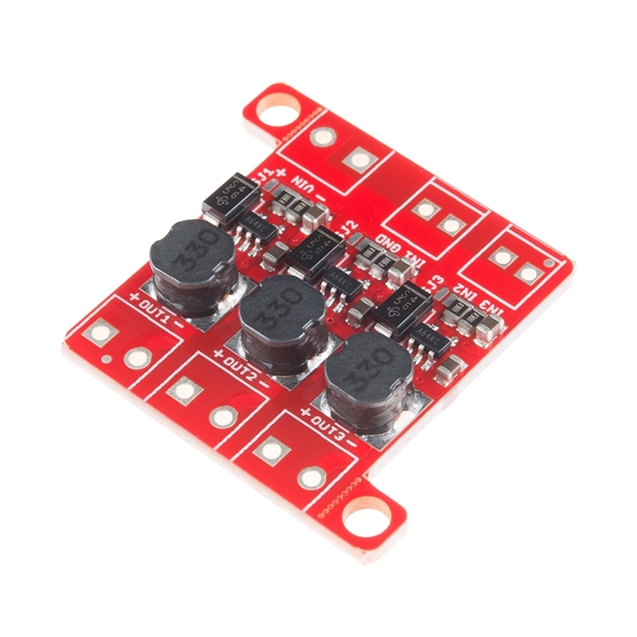
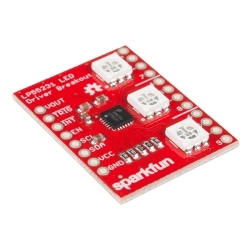
The PicoBuck LED Driver is an economical and easy to use driver that will allow you to control and blend three different LEDs on three different channels. Power is supplied to the PicoBuck through a wide range of input voltages (6v to 20v) connected to the VIN header and three inputs for each driver channel (labeled IN1, IN2, and IN3) driven with standard 3.3v or 5v logic.

This PicoBuck supports PWM control so long as the signal is above a minimum of ~1.5V and each LED is driven to ~350mA.

Note: If you're going to use screw terminals, this board uses two different sizes. Check the related products for both sizes you'll need.

Note: The PicoBuck LED Driver was made in collaboration with Ethan Zonca. A portion of each sale is given back to him.

PicoBuck LED Driver Product Help and Resources

Touch Potentiometer Hookup Guide

October 22, 2015

Learn how to use the SparkFun Touch Potentiometer to control lighting, volume or other inputs in your daily life.

Core Skill: Soldering

This skill defines how difficult the soldering is on a particular product. It might be a couple simple solder joints, or require special reflow tools.

2 Soldering

Skill Level: Rookie - The number of pins increases, and you will have to determine polarity of components and some of the components might be a bit trickier or close together. You might need solder wick or flux.
See all skill levels


Core Skill: Programming

If a board needs code or communicates somehow, you're going to need to know how to program or interface with it. The programming skill is all about communication and code.

1 Programming

Skill Level: Noob - Programming will be limited to basic drag and drop interfaces like ModKit or Scratch. You won't be writing code, but you will still need to understand some basics of interfacing with hardware. If you?re just using a sensor, it's output is analog.
See all skill levels


Core Skill: Electrical Prototyping

If it requires power, you need to know how much, what all the pins do, and how to hook it up. You may need to reference datasheets, schematics, and know the ins and outs of electronics.

2 Electrical Prototyping

Skill Level: Rookie - You may be required to know a bit more about the component, such as orientation, or how to hook it up, in addition to power requirements. You will need to understand polarized components.
See all skill levels


Comments

Looking for answers to technical questions?

We welcome your comments and suggestions below. However, if you are looking for solutions to technical questions please see our Technical Assistance page.

  • Grarup / about 8 years ago / 1

    Im looking in the documentation and it says that you can dim between 20%-100% by supplying from 0.5 to 2.5v. What happen at 0v? What is the max voltage the control pins can take?

    • SFUptownMaker / about 8 years ago / 1

      At below 0.5V the output is turned off, entirely. The maximum voltage on the control pins is 6V relative to ground.

      • Grarup / about 8 years ago / 1

        Thank you, do you also know how much current is drawn when it is off.

  • I've been playing with one of these in a test bed for my Aquarium LED setup.

    One annoying thing I've noticed is that when you first turn it on the LEDs are on full brightness until the microprocessor boots and takes over.

    As a test I added a 10k pulldown resistor between the PWM input and ground. This worked well an 0805 resistor sitting on it's side fits just perfectly on the bottom of the board.

    Do you think this is something you'd like to add to the design?

    I'm just modifying the eagle files now for me but I thought others might find it useful too.

    • bennard / about 8 years ago * / 1

      Arggh I wish I read this two weeks ago. I Eagled up a four channel version of this thing so I can run four 10W LED modules (for an RGBW) at 1A (peak) each, as part of a strobey party light setup. Fortunately I could fudge a little 0603 10k between the pins 2 and 3 on the AL8805s and get startup under control. But I will have to do a revision 2. My retinas are still crying.

      I am imagining the uC disconnecting from the board by accident and letting it run full speed till something catches fire in the beam. Definitely need pull-downs integrated with the board.

  • Jeshii / about 9 years ago / 1

    Awesome! This is working perfect for my arduino bike light project! BUT, I'm a little unsure of how to actually mount the darn thing. Any advice?

    • SFUptownMaker / about 9 years ago / 1

      For a bike light I'm going to use a two-part epoxy and just kind of slather it on. I'm using the strap from a defunct bike light as the base.

      Normally I use hot glue for a lot of these sorts of things, but I don't trust it not to get brittle in the cold or soft in the sun.

  • Member #331031 / about 9 years ago * / 1

    This doesn't drive strips that have a common cathode or a common anode. Do you have any drivers that do support common cathode or anode strips?

    EDIT: Actually, my question doesn't make sense after thinking about how PWM works.

    • ethanzonca / about 9 years ago / 2

      If you want to drive non-addressable LED strips, I'd recommend PWMing some mosfets. Current-limiting resistors are built into the strips, so you don't need a constant current power supply.

      https://www.sparkfun.com/products/12901

  • Billbo911 / about 9 years ago * / 1

    I'm having some unexpected behavior from the PicoBuck. I am running only two channels. One with a Red "3 Watt" LED and one with a Blue "3 Watt" LED. I am powering this with the +12vdc rail of an old PC power supply. I am controlling each of the channels with a separate PWM output from a Arduino Nano. I am reading two separate pots to set the output value used to drive each channel. [pseudocode analogWrite (BlueLEDpin, analogRead((BluePot)/4)] The problem is, it appears I have a lot of cross talk between the two channels. If only one channel is connected, I can control it's brightness without issue. But, if I have two channels running, both pots change the brightness of both LEDs. Using serial.Print shows that each value being written out is in the expected range of 0-255. There is no cross control happening there. This leads me to believe the issue may be in the PicoBuck it's self.

    Any ideas?

    [EDIT] I looked into the specs on the AL8805W5 and found it works more reliably with <= 500Hz control signal. Since I am using pins 5 & 6 from the Arduino, I may be getting ~980Hz . Additionally, pins 5 and 6 use T1 for timing, as does the "delay()" command. These two items combined may be causing the issue. More testing later. I will post the results [/EDIT]

    [EDIT2] Yes, it is as I expected, using D5 & D6 for PWM output, along with code that includes "delay()", is NOT a good idea. I simply moved the control signals to D10 & D11 and the PicoBuck worked perfectly. I am tempted to remove my original post, but if it helps someone else to fix a problem, then I am happy to leave my oversight posted. [/EDIT2]

  • tc123 / about 10 years ago * / 1

    I have a 10W RGB led that has 4 die in series for each color, the green/blue channels have a 10-11V Vf. Will this work with a 12V input?

    • ethanzonca / about 10 years ago / 2

      I think that should work fine. Considering the efficiency of the regulator and on-resistance of the switching FET (typically about 0.25 ohms) I don't think there should be much of an issue. the AL8805 should be able to regulate with ~1V of headroom, although I haven't personally tested it.

      • SFUptownMaker / about 10 years ago / 2

        I just tested it at about a 0.5V above the Vf of a string of blue LEDs and it works fine.

        Didn't check the efficiency though, so YMMV on that front.

        • tc123 / about 10 years ago / 1

          Thanks for testing it! I'm going to buy one to play with.

      • tc123 / about 10 years ago / 1

        Thanks for the reply, I'm going to try it out.

  • McIvan / about 10 years ago / 1

    PWM Noise? Crosstalk? I'm wondering if anyone has any experience working with these in parallel with a microphone or other high resolution analog sensors? Do these generate a lot of electrical noise that gets picked up by analog sensors?

    I'm considering these for my next project iteration, and looking to eliminate the noise caused by these constant current circuits. http://www.instructables.com/id/Circuits-for-using-High-Power-LED-s/?ALLSTEPS

    Thanks all! =]

    Details ( I can use high frequency PWM on my teensy3.1 at 10-11bit depth to escape the "audible" range of my FFT audio analysis, however I need to use 16 bit pwm, which gets easily picked up by my FFT. My diagnostics indicated the noise wasn't EMF from signal lines, but noise in the power rails likely from the pulse draw. This gets heard by the teensy on all sensors, even when my mic is connected to the isolated +3.3v of the teensy and separate analog ground. +5v 2A power from wall-wort otherwise)

    • AlexWaller / about 10 years ago / 1

      I built the basic picobuck circuit into a device and made it past 60601-1 3rd edition emission and interference testing with zero problems. I mean it was silent. Beautifully silent. If you do your own circuit board, make sure you follow the layout recommendation in the AL8805 data sheet, and put your inductor in the right place.

    • Nick Orlando / about 10 years ago / 1

      I have worked with Ethan Zonca a lot in applying this circuit for lighting and audio purposes. Keeping this short, I will say I have experienced audio problems with PWM and noise while driving high current LEDs. However, this is easy to fix. The 2.2uF capacitors help offset most of the noise generated by the current limiting switching, which is about 500kHz (well out of audible noise range). To eliminate the PWM noise which is created by line drops from the high current draw it really helps to add some bulk capacitance at the power input of the picobuck. I recommend a 10uF ceramic and possibly even a 20uF or more electrolytic depending on your wiring situation. The longer your power wires, the more bulk capacitance you may require.

  • stephan schulz / about 10 years ago / 1

    i was looking at your bill of materials, because i was wondering if this circuit could be driven with 24v. i need to make it work with an already existing architecture. you are mentioning higher voltage caps. would one also have to use a diode with a higher “Voltage – DC Reverse” ? I think the currently used diode has a rating of 23V. thx

    • SFUptownMaker / about 10 years ago / 1

      Yes, you'd probably need to replace that diode as well.

      The components selected were chosen based on availability (basically, what we have in stock already) and size (to keep the board size down). It's possible that there could be some higher-voltage replacements available out there that would allow you to bump the input voltage up to 24V.

      You could also just try it at 24V, depending on the nature of the application. Exceeding the voltage ratings <strike>may</strike> will shorten the life of the board; maybe that doesn't matter for your application.

  • stephan schulz / about 10 years ago / 1

    i am driving the driver with a PWM signal from a teensy micro controller. it works fine. but the datasheet says: "The CTRL pin is designed to be driven by both 3.3V and 5V logic levels directly from a logic output with either an open drain output or push-pull output stage."

    i know if i drive the rebel led driver (from sparkfun) with a regular PWM pin from an arduino it will burn the driver, because it too needs an open drain PWM signal.

    so why is the picobuck ok with using a regular PWM?

    • SFUptownMaker / about 10 years ago / 1

      Different driver IC with different requirements. It's all in the chip.

  • stephan schulz / about 10 years ago * / 1

    i'm interested to know how this led driver would compare to something like the TLC5940. certainly this one can handle higher amp leds but when using multiple channel of the TLC one could get similar or more current sinking. i guess i am just hoping to learn a bit more about the different options out there. thx.

    • SFUptownMaker / about 10 years ago / 1

      The efficiency gain for the PicoBuck is what makes it worth using. Because it's a switch-mode current regulator, it's capable of reaching much higher efficiency levels.

      Something like the TLC will have a very low efficiency- for a 3V LED in a 5V system, your efficiency would peak at 60%. The other 40% is dissipated as heat in the driver, which can destroy the chip.

      • stephan schulz / about 10 years ago / 1

        thanks for the info.

        so if someone would supply the TLC/LEDs with the right voltage (3V), by using a DC switching regulator (24V -> 3v), the efficiency would get better?

        I am not trying to find arguments against the picoBuck. it's a beautiful setup. I am just noticing that the TLC produces no flicker. See my other post. thx.

        • SFUptownMaker / about 10 years ago / 1

          Yes, reducing the supply voltage improves efficiency.

          Also, since the TLC is also a PWM-based dimmer, you'll probably see flickering with that too.

          • stephan schulz / about 10 years ago / 1

            using this opto coupler 6N137 did not work.

          • stephan schulz / about 10 years ago * / 1

            at this point i tried driving the picoBuck from hardware PWM and software interrupt PWM of an arduino and both method caused flicker.

            then i tried the TLC from an arduino and did not see flicker.

            my preferred option would be using 16 picoBucks via a the 16 channels of a TLC. maybe by using a optocoupler.

            here is a video with the picoBuck on the left and the TLC for the 2 leds on the right: https://www.dropbox.com/s/0srg5wrzc54czh5/2013-12-19%2015.52.10.mp4

            • McIvan / about 10 years ago * / 1

              Thanks for the video! I noticed two things in the fade on the left, the flicker (mentioned in a comment below) where the light appears to go off for second is looks like a recording artifact for 30 frames per second. I've seen it two through cameras, BUT you don't see that with your eye correct?

              Also there seem to be subtle, interior pulses as the brightness rises... Are those only from this driver? Overall, is the fade as smooth as a single 5mm LED in the basic Arduino fade example?

  • stephan schulz / about 10 years ago / 1

    the drivers work great with a PWM adjust signal. but when looking at the leds through a camera i can see flicker. the flicker changes depending on the PWM frequency but never goes away completely. i am wondering if you had any experience with using a DAC to control the brightness?

    • ethanzonca / about 10 years ago / 1

      I haven't driven a PicoBuck with a DAC, but I have tested analog control with a bench power supply as the control input. Just have your DAC generate a voltage between .5V-2.5V to the control pins. The control pin only takes microamps to drive, so you shouldn't need any buffering of your DAC's output. Keep in mind that analog control can only dim from ~20% to 100%, so you may still want PWM if you need low (<20%) brightness.

  • wgardiner / about 10 years ago / 1

    I tried to use a 19.4V Vin and the AL8805 on Channel 3 fried. This page lists the input voltage range as 6V to 20V. Is the range of input voltages incorrect or do I have a faulty product?

    • ethanzonca / about 10 years ago / 1

      If you haven't already, contact techsupport@sparkfun.com and let them know that your PicoBuck failed when operating within the product specs. PicoBucks have been run above 19v successfully, so you probably just got a bad board.

    • Kamiquasi / about 10 years ago / 1

      The AL8805 itself should be fine up to 36V according to its datasheet. It's always possible you just had bad luck with that component.

  • stephan schulz / about 11 years ago / 1

    would it be possible to use the WS2801 IC PWD pins to drive these LED drivers, since the WS2801 can only handle up to 150ma and the PicoBuck up to 700 ma.

    i used a ZXLD1350ET5TA led driver before, which looks very similar to the AL8805W5 but i needed an open drain pwd.

    • ethanzonca / about 11 years ago / 1

      Stephan,

      I'm unfamiliar with the WS2801, but it does look like you could use that IC to drive the inputs of the PicoBuck. The datasheet includes an app note where the WS2801 is driving external NPN transistors--all you're doing is replacing that transistor with a channel of the PicoBuck

      • stephan schulz / about 11 years ago / 1

        cool. i will give it a try. with my old circuit, as mentioned before i needed to set my micro-controller output to be an open drain, otherwise the led driver actually started smoking when driving it to full brightness - analogWrite(255). would this be a worry here too?

  • Member #471783 / about 11 years ago / 1

    Hi there,

    how do i adjust the brightness of each led that i am connecting to this thingy? I am hooking up an RGB LED that has individual leads for + and -. So far it always seemed that the Red channel is brighther than the others for example, so in order to make them mix nicely i need to do some adjustments, yes?

    Thanks, Dave

    • ethanzonca / about 11 years ago / 1

      Hey Dave,

      There are 2 ways you can adjust the brightness: apply a 0-2.5v analog voltage to each of the control pins, or send a PWM signal to each input. Check out the "Hookup Guide" linked above, it should point you in the right direction.

  • SurprisingEdge / about 11 years ago / 1

    The link to the GitHub page isn't working, and the protofusion site seems to be down. I'd love to know what the maximum LED current drive of this is, but I can't find that information.

    • Sorry about that. The GitHub page didn't have the correct permissions set on it. I'll get that fixed right away!

    • ethanzonca / about 11 years ago / 1

      The current drive of the PicoBuck is 350mA per channel (set by an 0805 current-sensing resistor). My site (protofusion.org) should be back up this evening! We just had a hardware failure.

      • SurprisingEdge / about 11 years ago / 1

        Thanks. Wow, that looks awesome! I've been trying to design (or buy) something just like this. I need to power 12 RGB LEDs (as 36 independent channels) with relatively high efficiency, at up to 700ma per channel. Is the efficiency of this buck driver affected much by the difference between the Vin and the LED's Vfwd? It looks like I could probably use 12 of these (4 for red, 4 for green, 4 for blue, with Vin on each set close to the Vfwd of that colour) with different current sense resistors (0.14Ω?) I guess my question is, would it be able to handle that amount of current, possibly with heatsinking?

        • ethanzonca / about 11 years ago / 1

          The PicoBuck should be able to handle around 700mA of current if you replace the current limiting resistors with 0.14Ω. I wouldn't go much above 700mA, as that is approaching the current limit of the diode. Also, if you don't need independent control of each LED, you can attach multiple LEDs of a color in series (as long as your input voltage is 1.5v+ more than sum of your forward voltages).

          A large difference between Vin and Vfwd (running a 2.5v led at 700ma from a 9v supply ) yields about 76% of efficiency. Increase that to a Vfwd=5v and efficiency jumps to 88%. In either case, you shouldn't need any heatsinking (as far as the numbers go).

Customer Reviews

4.5 out of 5

Based on 10 ratings:

Currently viewing all customer reviews.

2 of 2 found this helpful:

worked pretty good

Only thing that would be nicer is if it didn't turn on while controller is off

0 of 5 found this helpful:

bad contact

I asked some questions according the board, tried it 3 times and didn't get any answer. So the Resume: product ok - Contact and communication extrem bad / nothing. So i will buy never here.

Hello, It appears that we received an email from you on April 15, and replied to you the same day. We tried to answer all of your questions in that email. That's the last we heard from you. I'm sorry you were not satisfied with our technician's response.

Works as advertised

This is a nice compact with three LED current drivers at 350mA each. There is also a digital control input for each to switch it On/Off or Pulse Width Modulate the LED. As another reviewer commented the pins are on strange spacings. The power inputs and outputs aren't 0.1" spacing, they're 0.15". The signal inputs are strange too, GND and IN1 have a 0.1" spacing and IN2 and IN3 have a 0.1" spacing but between IN1 and IN2 it's closer to 0.15". Since most of the connectors I have are on 0.1" this is a little inconvenient but if you're just soldering wires it makes no difference. Also the Buck LED driver has a resistor that sets the current at 350mA. I think the chip and many LEDs are capable of 1A. Since the resistor is a small 0603 package it is difficult to change it to increase the current if desired. 350mA is quite brite, just curious to see what an Amp looks like!

works great

this little guy works really well and was even smaller than i'd figured. and was so easy to use with the PWM outputs from my netduino to control one channel each of RGB. my only complaint is that those resistors are surface mounted. would be nice to have an easier route to replace them for those of us without the skills/gear to work with them.

Another Excellent Product

I used the PicoBuck to drive three 13106 3W LEDs and it works perfectly.

Does the job with no glitches

Hooked this little guy to the Raspberry Pi and some powerful IRLED's and it drove them pretty well. I/O was easy and dimming was just as so. Only problem was the plethora of pin pitches for screw terminals. Making all of them the same pitch would have been nice for both purchasing screw terminals and lining them up on the board (awkward having different sizes).

Very well designed and does what it says.

This is a great little board for powering and controlling bright RGB LED's. I'm using mine to power the 3 channel RGB led from Sparkfun.

The board is very well designed. The only thing I could recommend to Sparkfun is breaking out another Vin+ so that the same source that is powering the LED's could be easily used to power an attached controller such as an arduino.

I simply placed a second wire in the Vin+ terminal to share the V+ and used the GND next to IN1 as ground since I was controlling it with PWM anyways.. Simple solution but may not work for everyone if your power source has large wires.

Otherwise this is a great board that is quite compact and does its job with no fuss.

Easy to set up

This was easy to set up. I connected 2 3 watt led's to it and attached all three components to a piece of acrylic. This was easy since everything is surface mounted giving a flat back for gluing or double stick taping. The result was a nice little task light.

Good solution

I use the PicoBuck LED driver with the high power LEDs on my 4WD robot and seems to be the right fit for it. I plan to use the PWM feature in the future. AC/.

awesome for synthesizer CV controlled LEDs

was easy to hook up, small, lightweight, and all around awesome.