SparkFun Inventor's Kit Guidebook - v4.1a
BOK-15884

SparkFun Inventor's Kit Guidebook - v4.1a
SKU: BOK-15884
$5.95
In stock
SKU
BOK-15884
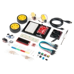
The SIK Guidebook V4.1 contains step by step instructions with circuit diagrams for building each project and circuit with the parts in the kit.
Product Overview
The full-color SparkFun Inventor's Kit Guidebook V3 contains step by step instructions of how to connect each circuit with the included parts. Full example code is provided and explained and even includes troubleshooting tips if something goes wrong. Once you make your way through all of the example circuits you will have a much better grasp on programming electronics!
Circuit Examples:
- Circuit 1: Blinking an LED
- Circuit 2: Reading a Potentiometer
- Circuit 3: Driving and RGB LED
- Circuit 4: Driving Multiple LEDs
- Circuit 5: Push Buttons
- Circuit 6: Reading a Photo Resistor
- Circuit 7: Reading a Temperature Sensor
- Circuit 8: Driving a Servo Motor
- Circuit 9: Using a Flex Sensor
- Circuit 10: Reading a Soft Potentiometer
- Circuit 11: Using a Buzzer
- Circuit 12: Driving a Motor
- Circuit 13: Using Relays
- Circuit 14: Using a Shift Register
- Circuit 15: Using an LCD
- Circuit 16: Building a Simon Says
Documents:
- PDF Version
- [SIK Code Library](http://cdn.sparkfun.com/datasheets/Kits/SIK Guide Code.zip)
- SIK V3 Wishlist
- Product Video
Replaces:BOK-11581
Similar Items


Hookup Accessories


Features & Specs
- For V4.1a an error was corrected on page 73 where VCC and GND pins on the LCD were connected to the wrong power rails
- This change is also featured on the SIK Errata page
Documentation
Customer Reviews

SparkFun Inventor's Kit Guidebook - v4.1a
$5.95
BOK-15884
Stock and Customer Discounts
$5.95 retail price.