SparkFun 7-Segment Serial Display - White
Helpful Documentation
 Hookup Guide
 Schematic
 Datasheet
Product Overview
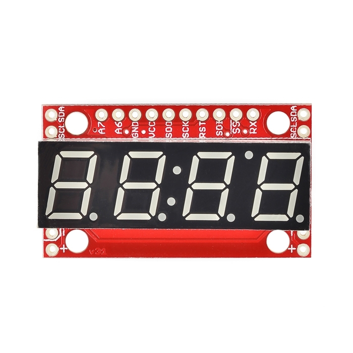
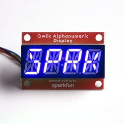
4-digit 7-segment displays are really neat little devices, it's a shame that they can be so cumbersome to control. Well we've solved that problem by making them a little bit "smarter." The SparkFun 7-Segment Serial Display combines a classic 4-digit 7-segment display and an ATMega328 microcontroller allowing you to control every segment individually using only a few serial lines.
The Serial 7-Segment Display can be controlled in one of three ways: Serial TTL communication, SPI serial communication or I2C serial. You can even program it for stand-alone operation since the ATMega328 comes pre-loaded with the Arduino bootloader! There is also an FTDI header on board and we've provided a hardware profile for the Arduino IDE to make it even easier to program.
We've made some layout changes to this design as well which will make it easier to incorporate these into your project. We've moved the power and I2C pins to the sides of the board such that you can chain them together in order to display longer strings of digits. We've also added mounting holes to the boards so you can mount them on standoffs (no more hot glue!)
Dimensions: 41mm x 23mm (1.6in x 0.9in)
Features:
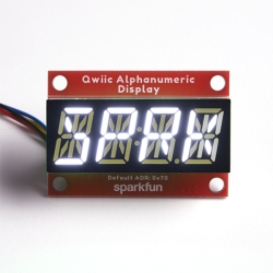
- 4 digit white alpha-numeric display with TTL, SPI or I2C Serial Interface
- Display numbers, most letters, and a few special characters
- Individual control of decimal points, apostrophe, and colon
- Selectable baud rate
- Selectable brightness
- Baud rate and brightness values retained in non-volatile memory
- Individual segment control for each digit
Documents:


Features & Specs
- 4 digit white alpha-numeric display with TTL, SPI or I2C Serial Interface
- Display numbers, most letters, and a few special characters
- Individual control of decimal points, apostrophe, and colon
- Selectable baud rate
- Selectable brightness
- Baud rate and brightness values retained in non-volatile memory
- Individual segment control for each digit
- 41mm x 23mm (1.6in x 0.9in)
Documentation
Customer Reviews

Stock and Customer Discounts
Available Discounts
- $17.58 | 10+ units
- $16.65 | 25+ units
- $15.73 | 100+ units