- Home
- Product Categories
- Distance
- SparkFun ToF Range Finder Breakout - VL6180

SparkFun ToF Range Finder Breakout - VL6180
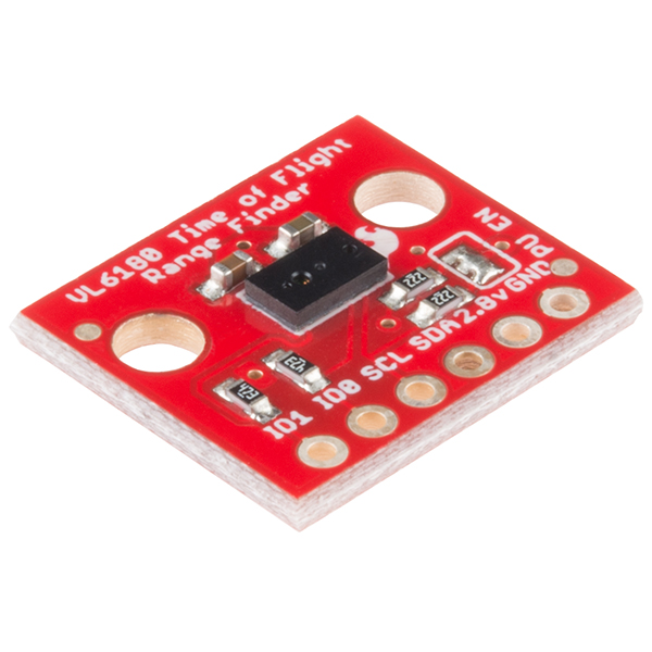
This is the SparkFun "Time-of-Flight" Range Finder, a breakout for the VL6180 distance sensor. Unlike most distance sensors that rely reflected light intensity or reflected angles to determine range, the VL6180 uses a precise clock to measure the time it takes light to bounce back from a surface. This affords the ToF Range Finder and VL6180 a great benefit over other methods because it can be much more accurate and more immune to noise. Does this technology sound familiar? Well it should, it's the same means cellphones use to detect when the caller is holding their phone to their ear.
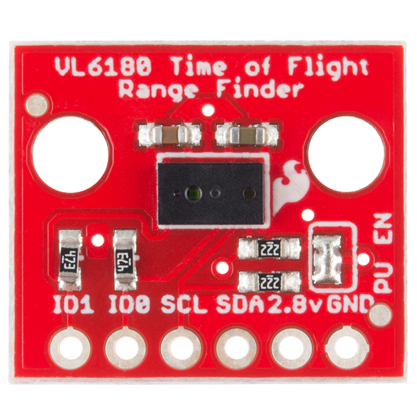
This breakout for the VL6180 from STMicroelectronics is as simple as it gets. Only the required passives are populated to give you the smallest, most cost effective way to use multiple sensors in a project with an I2C interface. The VL6180 is actually a 3-in-1 package that combines an IR emitter, a range sensor, and an ambient light sensor together for you to easily use. We've broken out each pin that is required to use the VL6180, including: IO1, IO0, SCL, SDA, 2.8V, and GND. Please be sure to note, however, the ToF Range Finder Breakout only accepts 2.8V input and logic. You must provide a 2.8V voltage source and level shifting to 3.3V and 5V devices.
Note: Though the datasheet states the VL6180 measures an absolute range of up to 10cm, we have successfully tested it up to 25cm. The more you know.
- Operating Voltage: 2.8V
- 3-in-1 Module
- IR Emitter
- Range Sensor
- Ambient Light Sensor
- Measures absolute range up to 10cm
- Gesture Recognition
- I2C Interface
- Two Programmable GPIO
- Two Mounting Holes
- Schematic
- Eagle Files
- Hookup Guide
- Datasheet (VL6180)
- Application Note (VL6180)
- GitHub (Design Files & Example Code)
- GitHub (Library)
SparkFun ToF Range Finder Breakout - VL6180 Product Help and Resources
VL6180 Hookup Guide
February 12, 2015
Get started with your VL6180 based sensor or the VL6180 breakout board.
Core Skill: Soldering
This skill defines how difficult the soldering is on a particular product. It might be a couple simple solder joints, or require special reflow tools.
Skill Level: Noob - Some basic soldering is required, but it is limited to a just a few pins, basic through-hole soldering, and couple (if any) polarized components. A basic soldering iron is all you should need.
See all skill levels
Core Skill: Programming
If a board needs code or communicates somehow, you're going to need to know how to program or interface with it. The programming skill is all about communication and code.
Skill Level: Competent - The toolchain for programming is a bit more complex and will examples may not be explicitly provided for you. You will be required to have a fundamental knowledge of programming and be required to provide your own code. You may need to modify existing libraries or code to work with your specific hardware. Sensor and hardware interfaces will be SPI or I2C.
See all skill levels
Core Skill: Electrical Prototyping
If it requires power, you need to know how much, what all the pins do, and how to hook it up. You may need to reference datasheets, schematics, and know the ins and outs of electronics.
Skill Level: Rookie - You may be required to know a bit more about the component, such as orientation, or how to hook it up, in addition to power requirements. You will need to understand polarized components.
See all skill levels
Comments
Looking for answers to technical questions?
We welcome your comments and suggestions below. However, if you are looking for solutions to technical questions please see our Technical Assistance page.
Customer Reviews
4 out of 5
Based on 1 ratings:
3 of 4 found this helpful:
voltages...
bummer that this was left as a 2.8v device. makes it really tough to do something with. Suggest in the next version adding a Vin pin and a small 2.8v regulator. Would make it immensely more friendly as an evaluation / breakout board.
When they work they work well, unfortunately the library and the setup makes it rather frustrating to get working...sometimes I get range data sometimes not.. I got 4 of these and only one works.
Also the tutorial for the hookup with the 317 is rubbish...simply doesn't work
I've tried everything to get the GPIO1 pin to actually go low. The I2C interface is working fine and I get the expected interrupt status when I query RESULT__INTERRUPT_STATUS_GPIO but electrically the GPIO 1 pin never fluctuates. Just to review: I'm setting SYSRANGE__START to 0x03 (continuous range mode), SYSTEM__INTERRUPT_CONFIG_GPIO to 0x01 (low threshold), and I've tried both SYSTEM__MODE_GPIO1 0x10 and 0x30 (active high|low) but nothing seems to work. Again, using AtmelStudio/DebugWire I can verify the I2C interface works as expected generating the appropriate interrupt status when polled. Has anyone had any luck with this? I'd like to put my MCU into deep sleep and only wake it up on interrupt when the sensor detects something nearby.
Warning to everyone about to buy this: the product description makes false claims about the ranging ability of the sensor. Sparkfun is claiming that this sensor "Measures absolute range up to 50cm", however this is not physically possible under ANY conditions.
To obtain a range measurement you must read the value stored in the RESULT__RANGE_VAL register. This is an unsigned 8-bit register that has units of mm. Since this is an 8-bit register, the maximum possible value is 255 mm. In other words, it is impossible to read a value higher than 25.5cm from this sensor.
An old preliminary data brief (that is now out-of-date) claimed up to 50cm for proximity ranging, however, ST has since switched to storing the range value in an 8-bit register which can no longer store values higher than 25.5cm.
dont you have a video of using this one?
Very soon.
Sparkfun, it is actually cheaper and way more flexible to go with STM's own dev kit!
http://ca.mouser.com/ProductDetail/STMicroelectronics/EVALKIT-VL6180X/?qs=sGAEpiMZZMvfpQN6QVmrfGjb%252b49cDybCa83Lgq8kEXU%3d
It is, but ST subsidizes their eval kits pretty heavily.
Indeed. They make the development tools cheap, so that you (or your company) are more likely to spend the big bucks when it comes to ordering components (their bread and butter) in high quantities. For SF, these types of things are their livelihood, so why shouldn't they make money on them? Even if you just look at it as a way of subsidizing the work they do in support of the maker community, it's still worth more than they charge in a lot of cases. I owe them thousands just for the time their Eagle and code libraries have saved me!
That may be true, but what happened to vendor loyalty. I find many things cheaper than at SF but I like to shop at SF :)
What happens when 2 of these are close by each other, do they interfere?
In the appnote there should be mention of crosstalk compensation. 5.1.1 Cross talk calibration procedure
If you were to use this to get the fluid level of a container... would it work? or does the light just travel through the liquid and provide an inaccurate measurement?
I think a clear fluid in a white or metallic container would have serious difficulties. Making the container black would help, and having a fluid that was dark or densely pigmented would help too. So I doubt this works great for water or gas-tanks. Measuring distance to a white float would be needed.
Adafruit would have put a 26 cent regulator and an I2C level shifter on their version of this board... Just saying. Seriously guys, the purpose of a breakout board isn't always just to solve the problem of people not being able to solder surface mount. How much does a PCA9306 cost in 250 count? 54 cents. To make the board a 'whatever you throw at it' voltage. The value of improvements like these are huge, and now you can plug it in to you Edison OR your Uno. With no extra crap!
We have a second version with level shifting and voltage regulation here. We are working quickly to get it back in stock.
Wicked
while we are in related topic; what should I use for distance around 50 meter for a car application?
Radar modules designed for that purpose can be bought cheaply from China. I'm pretty sure I saw them on AliExpress.
We have the LIDAR Lite, but it may not be great outdoors. Outdoor laser rangefinders suitable for automobiles are still in the thousand's of dollar price range. If you just need obstable detection there is a radar unit from delphi here. I think it was $800 last time I got one (life before SparkFun). Pretty cool but maybe not what you want.
Please consider linking to the actual data sheet, rather than just the product brief.
The datasheet is available here: http://www.st.com/st-web-ui/static/active/en/resource/technical/document/datasheet/DM00112632.pdf
A major point of interest that is deceptively challenging to find is how frequently the sensor may perform measurements. It seems as though there is a tradeoff as to whether one wishes to perform range measurements only, ambient light measurements only, or both.
I'm interested in just range measurements. The minimum measurement period according to the datasheet appears to be controlled by the SYSRANGE__INTERMEASUREMENT_PERIOD register. At its fastest setting (setting this register to zero), the range measurement period (when in continuous range measurement only mode) is 10 ms.
Note that this sensor's max range (according to the datasheet) is only 10 cm, but Casey (from SF) reports he can get reliable measurements out to 25 cm. Also note this sensor uses IR, so it may not work very well outdoors.
Datasheet and Appnotes are up now.
No, you don't have the data sheet posted. What your website claims to be a data sheet is actually the "preliminary data brief"; it is only four pages long, was written in Jan 2014, and doesn't include the register map!
The actual data sheet, available at http://www.st.com/st-web-ui/static/active/en/resource/technical/document/datasheet/DM00112632.pdf, was written on Aug 2014, is 74 pages long, and contains useful information not available in the data brief.
The full datasheet is up now. Thanks for updating!
The datasheet you linked is actually a very out-of-date preliminary data brief. Also, you can see in the official datasheet that the range value is stored in RESULT__RANGE_VAL, an unsigned 8-bit register with units of mm. An unsigned 8-bit register cannot store values exceeding 25.5cm, and I think your claim of "up to 50cm" is very misleading.
I first was very excited about this new sensor. But when I investigated it I discovered you are incorrectly advertising it as a 50cm sensor when it is limited to only 10cm. This is the official web: http://www.st.com/web/catalog/mmc/FM132/CL2136/SC1934/PF260441?s_searchtype=partnumber And the original datasheet (79 pages), not the very limited version (only 4 pages) you posted: http://www.st.com/st-web-ui/static/active/en/resource/technical/document/datasheet/DM00112632.pdf
Very disapointing to me. With a 50cm range it should have been a very usefull sensor, but a 10cm version does not make much sense to me.
Can you correct it?
Sorry about the confusion, as for the 10cm Range, I am reliably measuring ranges up to 25cm on my work bench. I think there was also some confusion on which data sheet to post. ST is fairly tight lipped when it comes to advanced sensors. The data sheets I worked from were released under NDA. Now that the sensor is live I see they changed their mind on what the sensor is capable of. I will get things updated ASAP. Thanks for pointing this out.
25cm also sounds good. But I am still confused. ST downgraded specifications from 50cm to 10cm? If ST only guarantees 10cm, but you get 25cm (2,5 times better), I think it will only work on very specific circumstances, is it? As nsa asked for, can you post a little video of it working at that distance?
What is the accuracy and resolution of this thing? Would be neat if could be used to level a 3D printer bed instead of an inductive probe.
1mm resolution, it has been shown to be fairly accurate +/- 1mm. Accuracy improves with calibration, I'll dig up the appnote I have been working with. There are a ton of parameters you can tweak to get better performance.
So it probably wont be of much use for leveling a print bed then?
Depends. If the repeatability is good (e.g. switches from 2mm to 1mm at the same distance from heat bed every time) then I can just work out the actual offset and adjust the slicer/firmware accordingly. Exact same process as the inductance sensor I use. The advantage over the inductance sensor (which is just an open collector on/off switch) is that I could vary the z axis feed rate based on the distance from the bed with less concern of it smashing into the head bed if it is travelling too fast. Of course spending extra money on this sensor over the cheap inductance sensor to save 30 seconds during bed leveling seems over the top if a print takes 5 hrs anyway.
There are plenty of other projects I'd like to try it out on though!
Ahh, but if you could use this instead of 'cheap' inductive probe, you could use any type of bed! No longer would you need to have bed of heavy metal. ;)
I saw a demo with .1mm resolution but I have yet to find the magic settings to make that work.
Edit: I looked back on all my data and I remembered this incorrectly. I saw 1mm resolution from the device averaged. From the data sheet it should be able to resolve to 1mm +/- 3mm.
Hi, do you mind providing a link to that demo please. As I'm very interested.
cheers Chris
Unfortunately it was not a public demo. :(
Was it an ST demo? As I've just given them an email to see if they can provide some information on how to get such an accuracy
We had an FAE come and show it off. They might have these floating around but I don't remember where to find it.
Edit: Found a link to a video that might help?
Cheers! I'll post on here if I hear back from ST