- Home
- Product Categories
- Arduino
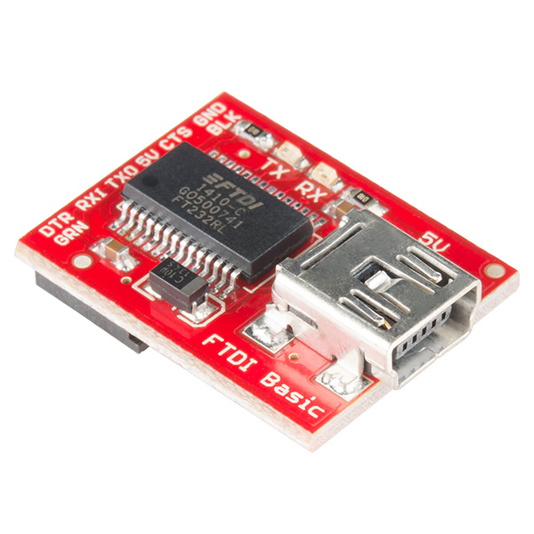
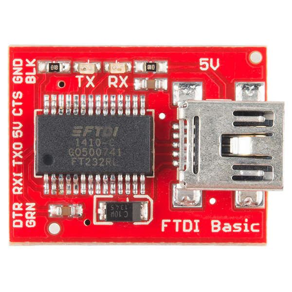
- SparkFun FTDI Basic Breakout - 5V

SparkFun FTDI Basic Breakout - 5V
This is the newest revision of our FTDI Basic. We now use a SMD 6-pin header on the bottom, which makes it smaller and more compact. Functionality has remained the same.
This is a basic breakout board for the FTDI FT232RL USB to serial IC. The pinout of this board matches the FTDI cable to work with official Arduino and cloned 5V Arduino boards. It can also be used for general serial applications. The major difference with this board is that it brings out the DTR pin as opposed to the RTS pin of the FTDI cable. The DTR pin allows an Arduino target to auto-reset when a new Sketch is downloaded. This is a really nice feature to have and allows a sketch to be downloaded without having to hit the reset button. This board will auto reset any Arduino board that has the reset pin brought out to a 6-pin connector.
The pins labeled BLK and GRN correspond to the colored wires on the FTDI cable. The black wire on the FTDI cable is GND, green is CTS. Use these BLK and GRN pins to align the FTDI basic board with your Arduino target.
This board has TX and RX LEDs that make it a bit better to use over the FTDI cable. You can actually see serial traffic on the LEDs to verify if the board is working.
This board was designed to decrease the cost of Arduino development and increase ease of use (the auto-reset feature rocks!). Our Arduino Pro boards and LilyPads use this type of connector.
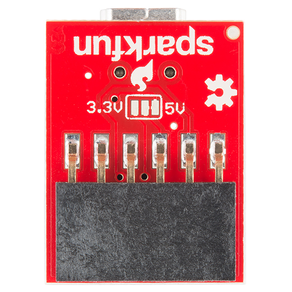
One of the nice features of this board is a jumper on the back of the board that allows the board to be configured to either 3.3V or 5V (both power output and IO level). This board ship default to 5V, but you can cut the default trace and add a solder jumper if you need to switch to 3.3V.
Note: We know a lot of you prefer microUSB over miniUSB. Never fear, we've got you covered! Check out our FT231X Breakout for your micro FTDI needs!
SparkFun FTDI Basic Breakout - 5V Product Help and Resources
How to Work with Jumper Pads and PCB Traces
April 2, 2018
Handling PCB jumper pads and traces is an essential skill. Learn how to cut a PCB trace, add a solder jumper between pads to reroute connections, and repair a trace with the green wire method if a trace is damaged.
SparkFun USB to Serial UART Boards Hookup Guide
February 18, 2016
How to use the SparkFun FTDI based boards to program an Arduino and access another serial device over the hardware serial port, without unplugging anything!
How to Install FTDI Drivers
June 4, 2013
How to install drivers for the FTDI Basic on Windows, Mac OS X, and Linux.
Dimensions and 3D Model
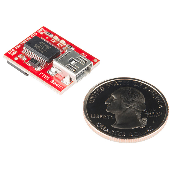
Measuring with a caliper, the board’s dimensions is about:
width = 17.91mm
length = 23.20mm (24.65mm measuring from the edge of the board to the edge of the mini-B connector sticking out)
height = 1.60mm (8.60mm measuring from the bottom header pin to the top of the mini-B connector)
There is also a 3D Model in our GitHub Repository here [ https://github.com/sparkfun/3D_Models/tree/master/products/9716 ].
Logic Levels
The FT232R won’t be 5V-tolerant when its VCCIO is 3.3V. Driving it this way risks harm to its internal 3.3V regulator.
1 of 1 found this helpful:
Converting FTDI from 5V to 3.3V
You can modify the board to make the 5V FTDI a 3.3V FTDI. The trace that connects the 5V pad to the center pad on the back of the 5V FTDI breakout board just needs to be cut with an XACTO/hobby knife. Then you need to add a solder jumper on between the 3.3V pad and the center pad. Here's a quick image => [ https://drive.google.com/file/d/0B0jwgLkjMWzDdXdCQ3k3UTR2a1E/view?usp=sharing ]. I would mark the board with a Sharpie to say 3.3V so you do not accidentally plug this into a 5V system.
Core Skill: Electrical Prototyping
If it requires power, you need to know how much, what all the pins do, and how to hook it up. You may need to reference datasheets, schematics, and know the ins and outs of electronics.
Skill Level: Rookie - You may be required to know a bit more about the component, such as orientation, or how to hook it up, in addition to power requirements. You will need to understand polarized components.
See all skill levels
Comments
Looking for answers to technical questions?
We welcome your comments and suggestions below. However, if you are looking for solutions to technical questions please see our Technical Assistance page.
Customer Reviews
4.5 out of 5
Based on 125 ratings:
1 of 1 found this helpful:
Works Great!
I used this to connect with an Atmega 328 that I had set up on a breadboard. The FTDI Basic communicated with the 328 to upload a Sketch on the very first try!
It is very nice that you do not have to manually reset the 328 in order to load a Sketch, and the TX and RX led's allow you to visually confirm that the Sketch is uploading.
NOTE: I read somewhere that you need to connect a 10 uF capacitor between the DTR line of the FTDI Basic and the Atmega 328 Reset pin. (I used this configuration, and it worked on the first try!)
1 of 1 found this helpful:
Great little device!
I bought three arduino pro units and one of these, and it worked great. The driver installed easily on windows 7, and programming was a snap. Very quickly I had replicated my programs and saved all the space and expense compared to an UNO or other full up board. Glad I made the purchase!!!
3 of 3 found this helpful:
Works as expected.
There once was a breakout from Sparkfun. So lovely! I went out and bought one. From host to Arduino, How nicely the bits flow, With nary a hint of dysfunction.
3 of 3 found this helpful:
Makes working with FTDI easy!
Sadly the Sparkfun tutorials for setting up FTDI drivers for Mac are out of date causing a bit of Googling to fix. After that, worked perfectly :)
1 of 1 found this helpful:
Awesome product
Easy to use, easy to work with.
1 of 1 found this helpful:
Works great for my Arduino mini pro
I designed a programmer board around the arduino mini pro to program a break light flasher board designed around an attiny85. Used Sparkfun's EAGLE library part for the arduino mini pro to design the board too.
1 of 1 found this helpful:
Works Perfectly!
1 of 1 found this helpful:
Out of the box hooked it up and it worked. that's all I need just good product. Thanks sparkfun Roadrunner
1 of 1 found this helpful:
Works fine on osx 10.10 Yosemite
Ensure you have a quality USB cable. A poor one rebooted my computer.switching to a better cable fixed the problem.
2 of 2 found this helpful:
This is my first ever Arduino Pro project and the FTDI board made my experience so easy... I just plugged it in and was able to start the Arduino IDE and communicating with the Arduino Pro board! I love-idiot proofed stuff like this!!
1 of 1 found this helpful:
Worked as expected!
Between the nice/solid/clean build (compared to imitations from ebay) and the documentation on the sparkfun site, this worked like a charm. Yes, it's a bit more expensive than other places, but the support/documentation is priceless. I've accumulated multiple SparkFun components over the past few months, and their build quality / documentation and performance is second to none. Keep up the good work.
4 of 4 found this helpful:
The item works as expected. I can only recommend it anyone needing a programer.
3 of 3 found this helpful:
I spent 4 months trying to update an minimosd with no luck ,if (failed to talk to bootloader) sounds familiar to you then you need this breakout board. Don't think a China board will do it . I bought 3 of those and an FTDI cable from China and it was to no avail.On one last desperate attempt I decided to go with a Quality product and I trust SpakFun and their products, service, and support. In a few days the board was in my mailbox and you know what, it worked the first time! I was able to salvage 4 osd's that I thought were bricked. If you're having trouble with any FTDI perpetual , bottom line is SpakFun FTDI Basic you won't be disappointed! !!!
1 of 1 found this helpful:
Solid device
Hardly my first purchase. I now have at least two at home and work. I remove the six pin header and run wires to a JST connector, and matching JST connectors to my Arduino's and have reliable polarity safe connections. I have cut the jumper and glued a small SPDT switch to one so that I can select 3.3 or 5V. To improve this board further I would like to see edge mounted LEDs that I could see from either side. Usually the thing is upside down the way that I use it.
1 of 1 found this helpful:
Just works
When I put together a DC boarduino from adafruit, I knew that it wouldn't work with USB directly, and didn't quite understand what this guy does until I just plugged it in! And it worked without any real fiddling. I also used the 3.3V version to reprogram the Big Time Watch from Sparkfun.
1 of 1 found this helpful:
works perfect
No issues at all, does what its supposed to do.
3 of 3 found this helpful:
Worked as expected
Never used Arduino boards before, ordered this with a couple of Pro Mini boards for a project. All worked just as builder described and has opened a new part of the hobby for me.
1 of 1 found this helpful:
Worked flawlessly.
Worked with my MacBook great, love that it includes TX/RX LEDs so I can see what's going on.
6 of 6 found this helpful:
Solid
Good solid design. One request... The connect should be a USB micro instead of a USB mini. Micros are more common and rated for more insertions.
2 of 2 found this helpful:
Compact and functional
I bought this to replace an FTDI cable, and found I like it better. I mostly use it with Arduino type devices, and it works just like I'd want. Plug it in, it powers the device and lets me program it and run the serial monitor. No fuss, works transparently.
0 of 4 found this helpful:
Hi..
I didn't received yet...! Eagerly awaiting for the post delivery.
Works as advertised
This is my first attempt at this Arduino stuff. I'm using this with an Arduino Pro, and everything worked first time. The auto reset works fine, and the serial leds are nice for verifying that everything is working. Price is very reasonable.
Works Great!
NO issues with this little fella! Works perfectly.
0 of 2 found this helpful:
FTDI Basic Breakout
So far I'm not able to "Upload", which is actually "Download!", any "Sketch" which is actually a "Program!" to either Arduino Uno or to a stand along setup as in Nuts & Volts Magazine issue April 2015, which I based my purchase on. Have loaded the FTDI drivers.
HI, You can try a loop back test to ensure the FTDI device is operating properly. You can also check device manager to ensure that they device is enumerating a com port for you. If you see an issue with the com port, then you may have drivers that are malfunctioning or have some other issue causing interruption with the device. Uninstall the driver and reinstall. If the Com port and the loop back are successful, then you can begin to trouble shoot your Arduino setup as the FTDI device should be operating properly.
Good Product
Works as advertized. Great service, fast shipping.
It works great
No problems at all. Immediate id with Windows 8.1, picked up a port instantly, not any problem down loading to my device. Excellent product.
Works great, no issues!
These are great little adapters for the smaller Arduino boards that save space by not including the programming hardware. Work just like the bigger boards, no difference, easy!
Programming of Minim OSD for Pixhawk
I purchased this to program my Minim OSD for a Pixhawk flight controller. It worked great for that purpose. I actually used it on the HK clone minim OSD (which is much less expensive) and I had no problem. If you purchase a Minim OSD, you will definitely need this to configure the flight screen.
Does what it says on the tin
Bought this to flash some arduino pro-minis and it works fine. This thing is tiny, so don't lose it.
Very easy to use and the led feedback is a real plus. Nice job !!
Breath of fresh air!
A few years ago, I tried to get into microcontroller programming. I tried the J-Stamp and the C-Stamp and had all sorts of problems. Those boards required a serial connection, but they didn't have any means of making that connection over USB. My laptop didn't have a serial port, so an adapter was necessary. I bought two of those, and neither of them worked very well. It was frustrating enough that I decided to stop playing with microcontrollers.
Then I decided to get my first Arduino. I stupidly tried getting the Arduino Pro Mini (the one that doesn't have onboard USB), and discovered that I would need more hardware to program the thing. That's where the SparkFun FTDI Basic Breakout comes into play! I plugged it in, drivers were installed, and everything just worked and continues to work! It's a new source of fun and I'm very grateful!
Thank you!
Works like expected!
The first one I received didn't work (didn't show up as device in Linux). Even though I only found out months later (you know, side-projects), SparkFun was so kind to send a replacement. Still working like a charm!
Works like a champ with knock-off Arduino Pro Mini board
Recognized by Windows 7, no issues, installed as COM 6. Plays nice with Deek Robot Arduino Pro Mini board clone.
Much better than the predecessor
It´s smaller and more stable than the old one. The 6 pin Female Header is now right on the board which makes it more stable. Standard FTDI Drivers which were installled by Win7 without Problems.
Very Cool
First tool I didnt build..and it KICKS BUTT!
Works great!
I bought this to program a Pro Mini 5V for a project with some high school students. I has done the jub admirably from day 1.
Essential for every toolbox
If you've graduated past your first Arduino to just about any other platform or package, you're going to want this handy breakout around. It's the most reliable and easy way to load code.
Just plug and go. Just make sure it's not pluged in backwards by fliping it over.
just what I needed
Using this to power my Christmas light display
perfect tool
it's perfect tool to update or reprogramme. . saves time and works perfectly. loving it
0 of 1 found this helpful:
It is an FTDI dongle, but not ideal for the Iridium module as suggested
The Rock7 iridium module page has a link to this product suggesting that it can be used with the iridium module. While it's electrically true, the connector is on the wrong side of the board and it will hit the modem module and can't be connected unless you bend the pins on the modem board.
Buy a standard 6-pin FTDI cable; it'll fit and there's probably less stress on the expensive iridium board.
Perfect device for the job
I am using the FTDI breakout to interface with the Sparkfun ODB adapter. It works perfectly to give the flexibility to connect to the PI or PC.
Interface for Anarduino board
We just started using it for the interface board for AnArduino board with a LoRa radio. We believe this will be a good board to use in PocketQube satellites.
Goodie
Works as intended, good thing this has mini-usb, personally I don't like micro usb.
Works as it should!
Very cool for building things that will be permanent and you don't want to tie up your main arduino, and its smaller. Worked pefectly, programmed easily. Just changed the model/port and bob's your uncle.
Works perfectly, and doesn't take much space
This is a great little board for programming the Pro Mini boards, and it is very easy to use. Great job, SparkFun!
Works Great!!
I use it to program the ardweeny the "One-Chip-Arduino" that is in most of my projects.
0 of 1 found this helpful:
Works but it's to wide..
Used this to program my arduino pro. If you solder on DC barrel power jack on to the pro, this breakout won't fit anymore. It's a couple of millimeters to wide. You then need to use female to male jumper wire. Off course I did not have this at the time, so I had to desolder the barrel jack, ruining my pro in the process.
Other than that, works like a charm.
Great programming interface
Bought this to use with Simblee. Works perfectly. There is a problem with the current Mac OS but works perfectly in Windows. I ended up putting in a Windows virtualizer in the latest Mac OS to make it work. That seems to be the best solution.....but not a fault of the board.
great item
Works great, just what I wanted. This has got to be the most obscure item for quads made right now. Joe W
Works in all my applications
Works in all my applications Where others did not
Breakout keeps mini-pro price low
I met an 8th grader who picked up two mini-pro boards for $0.68/each and used one in his team's project. I got ours for $3.33/each & could price out our devices lower w/o the USb circuitry we didn't need. The breakout does the job.
Works as advertized
Purchases the breakout board for use with some Sparkfun Pro Mini's for a work project. Other than needing to ID the board in the Arduino environment as a nano, the board works flawlessly.
Great ftdi that is simple to use
I really like this ftdi. It is the first one I have owned, and it works as advertised. I didn't have to find extra drivers for it for windows, or linux (openSUSE.) I bought it to work with my arduino pro mini. They should put in the description or somewhere that if you are on Linux and are having trouble uploading to anything that you need to add yourself to the group dial out. It is extremely simple in openSUSE, just go into yast and in groups.
Worked Fine
Plugged it in, hooked it up and transferred data. Just like it should.
The best thing I ever bought!
It worked like a charm! It will be the best programing component I ever owned and I would be lost without it. Thank you SparkFun!
OVER ALL A GOOD PRODUCT.
PROS: Small, easy to use. works as it should. CONS: Driver hard to install. Connector works but is not one of today's standard USB connectors, ie: USB mini.
Works just as it should!
The FTDI basic board worked just as it was supposed to. I'm not into arduino or any type of custom electronics, but I do build rc planes and multi rotors. I bought a cheap knock off OSD for a plane and not even the usb cable would work for me. I bought this FTDI board and easily configured the OSD with the computer.
did the JOB
Did the job. Used it with an ArduinoPro Mini
Easy to use.
Really nice device! Easy to use and just works.
Very user friendly
Im a total noobie at programing and this FTDI was pretty much plug and play. It worked flalessly and no glitching. There is nothing worse when programming the first time for the hardware to not be working properly and you thinking that it is because you dont know what your doing. This is why i chose sparkfun and not the cheap pieces on ebay or the slow boat from another country. They might have worked just fine, but forums pointed out that the quality control is not very good on the very cheap stuff
Excellent interface to the Arduino Pro Mini
It works reliably and quickly. My only concern is with the ambiguous way you can plug it in (clearly learning curve on my part). Fortunately, making a mistake is benign and simply results in a failed upload. I have a collection of old miniUSB cables, so I am able to use it as is. It is, though, becoming a little bit of an anachronism.
Works Fine
The connection between my mini usb cord and this breakout fits pretty tight so make sure it's pushed all the way in until it clicks!
Error: [...] programmer is not responding
All connections made, FTDI drivers updated, USB cable replaced, soldering checked, but I'm still getting the same error: avrdude: stk500_recv(): programmer is not responding BTW: I'm using Linux
This device has worked flawlessly since day one.
It does exactly what it should do.
I was able to program my Arduino Pro Mini without even soldering headers to it. My only wish is that this device have a header or a switch to program the 3.3 as well as the 5V. I know I can jumper it with solder but then I'd have to unsolder it to go back to 5V
Does exactly what it's supposed to do every time.
Not much to get excited about over an FTDI breakout but this product has never not worked. I've used it as the power source for a project for months and it never stuttered. Bought this second one because I'm still running power through the other one for that project!
So far so good.
It has been a long time since I worked on this stuff so I have to go back and review. Working on it.
Fast, hassle free shipping for this and a purpletooth jamboree
I ordered this along with a Purpletooth Jamboree very close to the end of the day on a friday. Drooling at the prospect of a full weekend tinkering away I went ahead with overnight shipping and figured I would let the chips fall where they may.
Sparkfun did not disappoint. Boards left that same night and I recieved them before noon the next day. Products were fantastic, and well documented. Easily exceeded expectations.
11/10 Would buy again
Great device
A low cost way to be able to bebur the signal flow between USN and TTL.
love it simple and adaptable
Indispensable. no complaints, powers and allows me to upload sketches without issue, I only wish it were more convenient to switch between 5 and 3.3 V modes
switch to 3.3V
If I cut the 5V line and solder a jumper to 3.3V, does this mean the Tx/Rx level also operate than with 3.3V instead of 5V? Or is this only for the power output? It isn't clear for me from the schematics.
Haven't had success with it yet.
I've been trying to use this to program the Adafruit Pro Trinket 5V. So far, I've had no success, the device does not show up under Windows 10.
I haven't rated this lower because there may be a way to get it to work that I haven't stumbled upon. I also don't know for sure the problem is with this device, though not being able to find it in Windows 10 makes me think there is a driver issue.
Hello!
Have you reached out to our technical support department @ techsupport@sparkfun.com ? They're usually pretty great at getting these working for people. You should contact them and see if they can help you get it up and working as expected.
0 of 1 found this helpful:
Not used yet !!!
Too many projects, too little time.......
Comes in handy... ;)
This module is a nifty little tool that helps a great deal employing microprocessors. All the necessary pins are broken out and the 5V / 3.3V option adds to it even more. I use this to resemble an Arduino-kinda-circuit in my project so that reprogramming the 1284P-PU in-circuit works like a charm. - Well done - good job, team!
Works exactly as advertised
I'm completely satisfied. I use it to program an Arduino Pro Mini, and it couldn't be easier. I like the fact that after programming, I can unplug the breakout board to save space in my final design.
Works great and easy to use.
I chose this device over other similar ones because I thought it would better fit my needs, now and in the future. And it does. The drivers loaded easily on Windows 10. Programming the Arduino Pro Mini 5V/16Mhz is a snap with this unit. I like being able to unplug it to save space in my completed project. Thanks, Sparkfun, for the great tools and gadgets!
Works perfectly, delivered very quickly
As usual, our Sparkfun order from half-way around the world arrived faster than local delivery services can deliver. Works perfectly. Compact design. Cheaper than a competing product that was out-of-stock.
Great little board.
This is a great little board, we both the 3v3 and 5v version at work. For my own projects, rather than adding the ftdi chip to the project is is much easier to drag serial lines to a 0.10" header.
Don't forget to switch RX and TX
If plugging this into a custom AVR (e.g. a breadboard no existing FTDI connection), don't forget to switch the TX and RX pins. These refer to the hosts transmit and receive, and should be connected to the opposite pins on your micro-controller for it to communicate properly.
Must have
This is prob one of the most useful things you can get from SF.
Yes it is excellent.
Notebooks no longer include a 9 pin serial port. For electronics that communicate with a serial, this is the product that will save you. Yes there are serial converters, hard to find but exist but, this will resolve this issue for good. More important, it is very helpful when you need to tap in to your serial connection and introduce changes when using a USB port.
Works great
I used this in a programming fixture for ESP8266s. Works fine.
Someday I would love one that breaks out both DTR and RTS; I don't care about CTS. That would allow automatic reset of the ESP chips. In the meantime, this seems like the simplest board out there for programming similar modules in a semi-permanent fixture.
works great with my osd mavlink
I was connecting through ftdi with with single wires and it worked but it was a mess! with SparkFun FTDI Basic Breakout I can plug the unit straight in and then the only wire is the usb cord. Fantastic glad I found it. By the way I found this item on an instructional Painless360 video (APM 2.5_2.6_2.7 - Adding an OSD for FPV using MinimOSD - complete setup). I also saw it on another video on youtube having to do with the same subject were he gave the actual part no. for SparkFun
Bought 2. One works one does not.
How in the heck do you connect this to an Arduino Mini pro? Do you need a cable or a cross over cable? The pin definitions on the FTDI PCB and the pin definitions on the pro mini do not match. Do you need to do anything with the 3 surface mount pads for 5V or 3.3 V selection? Do you need to solder any of these pads?
Ok here is the scoop.
The program socket and Arduino do NOT require a crossover cable. Just solder a 6 pin header on the Arduino Mini 5 volt and plug the FTDI socket right onto that header.
The FTDI is default layed out for 5V. It is already in the traces, so you don't have to worry about those surface mount tabs. You do need to solder to these if running the pro mini 3.3 volt version.
I bought the 5v version because I needed to run the lumenati LEDs which run on 5 volts and require 5v logic. Plus the Atmel (now owned my Microchip) runs twice as fast on 5V then it does on 3V.
I bought two but only one seems to work. I don't know. I alternated both FTDI in circuit so I don't think I fried it. I will update when and if SparkFun replaces it.
Jeff Mechanical Engineer
Solves the Arduino ecosystem issue
Lots of great projects have been built using Arduino hardware. Some of them are worthy to graduate into the world of actual marketable products. But it is expensive, wasteful and kinda dumb to ship a real product with an Arduino Uno inside.
This little FTDI board allows you to graduate from the Uno to a real product without changing the code at all. Probably many will want to change the code anyway, or use a different processor, but if not you can just design your board with a 6 pin header for this FTDI Basic board and code away.
Why five volts? In today's microcontroller world, 5V processors are a specialty item. But the processor in the Uno can only run at 16 or 20 MHz if it has 5V. The 3.3V version can only run at 8 MHz. Maybe with some work you could graduate to a more sophisticated processor, but there are many of these inexpensive ATMEGA328P devices in distributor stock and lots of compatible code and libraries. Why fix it if it ain't broken?
The other great advantage of this little FTDI board is that you only have to have one for development. The actual shipping product can be like the Arduino Pro Mini 328 https://www.sparkfun.com/products/11113 , about 16 parts total. Then you add your secret sauce to lock doors or control drones or whatever and off you go.
One minor caveat - in production you need to order pre-programmed parts or add a 6 pin ICSP connector to program the blank parts with a boot-loader before the FTDI will work. But if you are really in volume production you would probably order pre-programmed parts anyway and just use the FTDI for debug or test tasks.
Please note that in all this you would respect the Creative Commons and other licenses that would apply to derivative products. In most cases that just means a note in the owner's manual crediting the originator and/or publishing the open-source part of the code if you have made changes.
Works great
Works great, never had a problem with it.
Good basic function block
When you happen to need something like this, this is a great way to tack USB connectivity onto something that doesn't have it or need it most of the time.
A row of .1" plated through connection points would be very useful along the edge where the "DTR ..RXI ... ..." labels are located.
Get it to work in windows 10
I used this to program my arduino mini pro. It works perect. I had to struggle a bit to get the ftdi driver working.
Excellent device
It is the FTDI device that should been included in the Red Board PTH that was available as a Retail Kit several years previously. Because like everything FTDI designs, and Sparkfun assembles, it just works.
Works great
Works great. Very tiny, so don't lose it!
Its breaking out 5 volts all over the place!
Works as advertised! I am building a network of Arduino Smart panels and needed a way to see what was going on at both ends of the network. I already had one of these I use to program and debug a single board at a time. Adding this little guy gave my project the Super Power to get those all important debug messages over the USB port from both the communicator and the communicatee processors. Now I can find my stupid mistakes and design flaws faster than ever.
so darn handy
have used these for multiple projects or as tool to interface with many projects. Have used with most other equipment but sometimes the software will not recognize the device as a comport. has nothing to do with this device. Think some manufactures do things like this to buy their product which is over priced for what it does. Only down fall is so small that gets lost in the land of projects at times.
Worked first try out of the box.
Just starting to play with the Arduino system, Wanted a small form factor for permanent items and ordered this to allow programming of the Pro Mini board. Board and Breakout linked and loaded the program without any problem. :-)
BEWARE !!!!!
When this board is jumpered for 3.3volts IT STILL POWERS UP AT 5 VOLTS BEFORE SWITCHING TO 3.3V. Not good !!!!!
A useful tool
I only work with the Arduino series of micro-controllers.
I tend to develop on the Arduino Uno, but will make an occasional product using the Pro mini as an embedded device. This demands that I used the FTDI as a method to pre-program the pro mini prior to placing it in a finished device.
I have 3 of the spark fun FTDIs on hand to avoid a work stopping failure of one of them. Needless to say, none have ever failed. They interface with the Arduino Pro mini perfectly.
Works as advertised
Does the job! I had to fiddle around with driver update to get it to work, otherwise would have given it a 5 star.
It is a good piece of hardware.
If it works, I am happy!
Works great for my breadboard Arduino
Does exactly as advertised, it's smaller than i expected, but that's a good thing.
Better each time
This batch is better than the last batch. And best ever customer support!
Decent little breakout board
Really easy to use, drivers install immediately and I can plug it right into the UART port on a micro or other embedded device and send/read data from my PC's COM port. It's much smaller than previous versions which is nice, as well as the fact that the UART header is simpler and smaller. Overall another great product from Sparkfun.
Works like a charm
Used this 5v BO for setting up a MinimOSD. When first plugging in, the required drivers automatically download then the following link is needed to complete: https://code.google.com/p/arducam-osd/downloads/list?can=2&q=MinimOSD&colspec=Filename+Summary+Uploaded+ReleaseDate+Size+DownloadCount
Additional tips: https://code.google.com/p/arducam-osd/wiki/minimosd
0 of 10 found this helpful:
dont know didn't use it...
Atmel Studio 6.2 failed to link my project. returned to Microchip their tools actually WORK. got no time to be playing around here with stuff that doesn't.
Sorry to hear you had a bad experience. These are actually great little boards, not sure why you had an issue.
Works fine on osx 10.10 Yosemite
Ensure you have a quality USB cable. A poor one rebooted my computer.switching to a better cable fixed the problem.
So easy to use!
I'm old school, (discrete components...even vacuum tubes!), and I'm amazed how easy this is to use. The best feature is the transmit/receive LED's. It's a great troubleshooting tool. This product has simplified and helped me to get 'caught up' on the newer technology at a good price. Thanks!
Workes as advertised
Simple, easy and works.
perfect price and function
bought this to flash my minium osd for a recent 250 fpv build did the trick. shipped quickly. great little tool
Works really well
Just like plug and play! I am 68 years old, dumber than most rocks and had no problem using it. Casey
Does the job
No complaints
Solid replacement
replacement for a device that I had fried, works very reliably
Exactly what I needed!
Needed to use an Arduino in a very small space and I substituted it for the Arduino Mini Pro and the Basic Breakout and it worked for exactly what I needed. Very easy to setup and figure out!
Works Perfectly
No issues right out of the box.
0 of 1 found this helpful:
I only needed it to work once. It did its job.
I only needed this to flash my minimosd. Plugged it in, drivers (Windows 7) were automatically found and downloaded via internet. Recognized as a COM port. Plugged in minimosd and flashed it.
Easy.
My Prominis, gone silent.
SparkFun skillfully anticipated proprietary trouble. For many reasons I'll see if I can get along with just one.
It's mini usb perfectly suits my needs.
I really wish it had mounting holes.
When I do the loopback test (connecting the RX and the TX pins) on my FTDI board only the Tx indicator LED lights up? Should the Rx LED also light up?
All connections made, FTDI drivers updated, USB cable replaced, soldering checked, but I’m still getting the same error: avrdude: stk500_recv(): programmer is not responding BTW: I’m using Linux
I'm sorry but technical support does not work off the comments. I just saw this when working on another case. The error output that you are seeing can be due to a number of reasons.
The value of the “sync resp” is different and not always the same, so it’s hard to say. It can be due to the FTDI drivers, USB cable, board selection in the Arduino IDE, the Arduino IDE version, bad solder joints, the Arduino is not being powered with a sufficient power supply, flux residue, etc. Besides checking some of those causes listed above, I sometimes use a search online with the error. Sometimes I find some solutions provided online through the Arduino.cc forums or other sources.
If you are still having issues using our FTDI, you can try sending technical support an email for further assistance to see if we can help you with the problem => https://www.sparkfun.com/technical_assistance .
I love how damn near every product is now explicitly marketed for, if not tailored to, Arduino. Guides/tutorials/etc. don't even bother with other options anymore. They just straight out assume you're an Arduino person. Sad for pretty much every newcomer to the hobby. In my own experience, whenever the topic of digital electronics/embedded programming comes up for the first time with a newly met techie they invariably say: "Oh yea, you mean Arduino. I just started learning that!". And it makes me ill. I know I'm not the only one, but I'm also aware of the prevailing culture of our time, i.e. if you ridicule that which is popular, brace for attack from the fan boys looking for pats on the back from the cool kids (i.e. the powers that be, e.g. mods). But yea, anyway... I suppose I should look on the bright side - they haven't started manufacturing "special" passive components for Arduino. Yet.
If you have ideas of products you would like to see that are not Arduino-compatible and are based around a different platform, please let us know. We want to provide our customers with the products they want to use!
I've been using my FTDI basic to program arduino pro minis for years without any problems, until today when it bricked two in a row. The FTDI is 5V, the pro minis are 5V, but after trying to program them, they are now unresponsive. My other FTDI is able to program other pro minis, and my voltmeter says that the board is at 5V, but now I'm freaked out. Do I just toss the bad FTDI basic and buy a new one, or should I be worried that it is something else? I did notice in the last few days that when I had it plugged in and opened a serial terminal and then after closing it, the pro mini would start to blink like crazy, like it was constantly and quickly being reset, until I unplugged the USB cable.
The schematic for this part shows 5V at the right is connected, but beneath the trace says, "Default 3.3 V"
Sorry about that, the 3.3V and 5V boards have the same schematic except for that jumper, it looks like we just forgot to change the note.
I already use one of these and want to purchase another one. I'm curious how my Mac will "see" the second FTDI break-out board while I've got the first one connected. By "see" I mean what do I see in the list of available Ports in the Arduino IDE app.
TIA.
Would this work with raspberry pi 2?
I wish this was listed/ linked above. It would have saved me HOURS!
FTDI BASIC Side***********Arduino Side
Actually, CTS must be pulled low, or else the chip can stop transmitting, as per the hardware flow control. So the connection diagram looks to me more like this:
For a breadboard arduino, connect DTR from the FTDI basic to a 100nF capacitor to Reset. Also, connect a 10k resistor from reset on arduino to +5V
Thanks for this, purza. Yes it could be good to have a link to this at the top in the description.
I have not been able to use the FTDI to connect to an Arduino on a breadboard circuit. See Makemagazine's Arduino Primer in volume 25, page 62. I see in the Sparkfun Forum re the Arduino that others have had this same error with the FTDI basic breakout -- not in sync error. They have used the FTDI with various Arduino boards. Can you provide more info on interfacing the FTDI board. I have installed the FTDI drivers and see the com port in windows XP and the Arduino IDE. Do I need to buy a different USB- TLL adapter?
I know this post is old, but for anyone else like myself reading these for help, this will hopefully shed some light. I had the exact same problem with my arduino, the not in sync error. After a lot of trial and error, mostly error and some research, i got it to work with a breadboard arduino! Tested this on arduino uno bootloader on an atmega 328 DIP and a lilypad bootloader with atmega 168 DIP. Pins are the same for these two, I have no idea for others. Connect like thise: FTDI Basic............Arduino DTR......................100nF capacitor (should say 104 on it)-->Reset (pin 1) ALSO, connect a 10kohm resistor from pin 1
on ardruino to 5V, this part is what had me messed up for so long. RXI........................TXD (pin 3) TX0.......................RXD (pin 2) 5V.........................5V power rail or whatever you are using CTS......................GND, I don't know why, but mine is working like this so I leave it alone! GND......................GND Good luck!
Sir, You are a gentleman and a scholar. Thanks very much for this info. Such a simple solution, and why wouldn't the people who sell this part make this info a priority?
Most people would be using this with a diy bread boarded atmega burned with the arduino bootloader. (What else would we be doing with it?). You need to have that 100nf freaking capacitor installed there!
I was about to throw this in the garbage. To further confuse things it has +3V printed on the 6 pin header, however it should say +5V (if you bought the +5V version!)
Dear Sparkfun people could you please add this info to the product description of this item to save other customers from perhaps hours of wasted time?
This seems to be a recurring issue with Sparkfun merchandise. A good company and good service, however you need to pick up the slack on some wrong product data, and info.
I'll see about finding a way to add this, but an ATMega328 on a breadboard is actually probably less than 1% case for the use of this board. It was designed for and used mostly with boards such as the Arduino Pro Mini and Arduino Pro that have the FTDI header on them for programming. A lot of people also use it to connect to boards such as the 9DOF Razor or a GPS module that output a serial stream. We rarely see people using this with a breadboared Arduino. But yes, that capacitor is needed as part of the Arduino's autoreset circuit, without it you would need to reset it manually.
I think I thought of a way! Copy and paste the above comment into the description. Haha. Actually, I usually go to the comments first when I have a problem, but I went looking for a tutorial first this time. I finally made it back here and the solution was right there waiting for me. I would also point out that under the "Customers also purchased" section the number two item on my page is https://www.sparkfun.com/products/10524 the Atmega328. Doesn't that mean that many people who look at this item also look at the bare ATmega used for breadboarding an Arduino?? Not a big deal; it just seems like an easy fix.
Thank you very much. The capacitor solved my problems.
Thank You Very Much I had the same problem but you solved it.
What size/style/type USB connector is on this?
It is miniUSB.
It appears to be miniUSB or microUSB from the comparison picture with a quarter.
Can we PLEASE just get a version with a 3v/5v switch on it... I would gladly pay 2-3 more dollars... and thats a 50 cent part not even.
Hey, is this what you are thinking about? I found this FTDI breakout board that has a 3v/5v switch on it.
http://store.ckdevices.com/products/FTDI-Pro.html
make one :)
We used a solder jumper switch rather than an AYZ or something of that nature to reduce the possibility of having to do a smoke test. If you are decent with a soldering iron you will be able to solder a surface mount switch to the solder jumper switch's pads.
You could just replace that solder jump with a switch footprint.
N8B,
My concern about releasing vital smoke is precisely why I did NOT suggest a switch; I suggested a male header, for which one would have a choice of connection methods (soldering, wire wrapping, jumper clip).
I accept that none of these is fool-proof, but neither is the solder jumper. I can, I regretfully assure you, forget which way I've solder bridged something. ;o{ As I've said for years, if you invent a better "fool-proof" system, someone will invent a better fool. :o}
If one were to have only 5V or only 3.3 V devices, then using a solder jumper would strike me as reasonable. If, however, one has both, it is (to say the least) darned inconvenient to have to fire up a soldering iron to move an interface device from one uCTLR to another. Therefore, I repeat my request for a male header.
On the topic of DIY modification: What's the spacing on the pads? It appears to be substantially less than 0.1 inches. I took a quick look at AYZs, but didn't see anything that has pin pitch that appears to match the pad pitch. If you could provide the pad spacing and hints as to where to find male headers or switches that match it, that would be a great help.
TIA,
Eric
If you have a soldering iron, why don't you just do the needful?
I believe they stuck to this design because adding a 3.3V/5V switch might be too risky. Forgetting the switch at 5V and plugging it to a non-5V tolerant 3.3V device would result in instant magic smoke. Probably.
Hi all- we had a silk screen printing mishap - if you receive one of these boards that has 3.3v printed between TXO and CTS instead of 5v, you should still be fine using a 5v power supply unless you cut the trace and add a jumper as described above.
Heads up everyone. Just received this board ~1 year after the original post and Sparkfun does not seem to have sold out of this batch yet. The silk screen still says 3.3V but it measures 5V.
Same thing here, just looked at mine!
Hello, can I use this FTDI Basic to program an ATMEGA or ATTiny via the ICSP using the Arduino IDE?
Thanks, Tony
No, this board is a USB to serial adapter. If you want to use the ISP header to program an AVR you will need an AVR programmer. This is usually used when you have the Arduino bootloader which allows you to program the board over a serial connection.
can i program an attiny85 with this?
In principle, you could, if you had an ATTiny85 with a bootloader that used software serial. But a bootloader would seriously cut into the flash space of an attiny. I don't think anyone seriously uses other than AVR programming for them.
Sorry for the noob question, but what's the difference between this and the pocket programmer?
The older version of the FTDI board had proper through-hole soldered pins. The 6 pin header socket on the latest verison is surface mounted!! This is a terrible design, and a poor way to save a few cents. The 2nd or 3rd time I plugged it in, it wouldn’t talk to the Arduino. I closely examined it, and found the track had been broken on the 1st and 2nd solder pads.
This is no surprise, as it is a mechanical component, soldered to pads at the end of hair-width traces on the board, and has no mechanical structural support. It only took a slight lift as I handled it to break 2 tracks. I am not a clumsy person, and was very disappointed to see it was destroyed in about 2 hours.
All it needed was to be glued to the board and this would have been avoided, or remain with the through-hole pins. It is very poor design. I have no way to repair such a small circuit trace. I have managed to get it to work, but it is very ugly and will not last long.
@Sparkfun - Please revise your motives for making the header socket SMD. It is poor design.
Through hole is available still
http://www.sparkfun.com/products/10008
The chip on this gets really hot (can't keep finger on it for more than a couple of seconds). Hot hot should it get. Also Windows 7 64bit is proving a bit of a challenge for drivers.
It shouldn't get hot at all. You may want to contact techsupport@sparkfun.com.
it would be cool if there was a switch (or solder jumper, whatever) to pick between bringing out DTR or RTS - that way it could also be used in place of the FTDI cable if needed
Nvm
Anyone know the Dimensions?
If the Eagle files are right, then 0.9" (22.86mm) by 0.68" (17.34mm). No idea about thickness - but could probably guesstimate that based on standard board thickness, the header and the mini USB port.
Can this be used with the Sparkfun PTH Redboard kit? I'd assume so, but it looks as if the boards might mechanically block each other.
Any chance you guys are working on a version of this which uses a chip from a more friendly manufacturer? I have a 3.3v one which works great, and now need a 5v one (soldering back and forth is a pain), but I don't want to support FTDI.
In their recent "Ask me anything" live session, I believe they mentioned they were going to make boards using Cypress's offerings - but the time frame for these appearing here was weeks. If you are interested in alternatives to FTDI, try this thread at eevblog which covers both chips and some ready-made products: Alternatives to FTDI USB to UART converter
Can this be use with an adapter cable to interface the arduino to a flash drive for mass storage? Are there any examples of this process?
Nope. Whenever you use USB one of your devices needs to act as a host device. Usually this is your computer and now a lot of smart phones and tablets can do so as well (this is basically what OTG is). But neither the flash drive nor the FTDI are host devices. It is possible to get a USB host shield for an Arduino, but you basically have to write your own drivers for the device you are using. I usually recommend using an SD card as they are much easier to interface with than a USB device.
The auto reset doesn't work for me. Here's the solution I've found: http://stackoverflow.com/questions/19765037/arduino-sketch-upload-issue-avrdude-stk500-recv-programmer-is-not-respondi
Can this board be used in reverse? I want to give USB capability to my serial device.
This is just a USB to Serial (TTL) interface. The data will go both ways so it should work fine as long as you are not trying to turn your serial device into a USB host (that's a completely different ball game).
Hi, i brake the SMD 6-pin header of this board. Were i can buy this connector? I dont find :s
Thanks a lot
So should I use this or the FTDI Cable to program an Arduino (the difference being DTR and RTS)?
Either will work fine. I like the FTDI board since I have enough cables on my desk, but they will both work fine.
I bought one today. solder a switch so you can choose 3.3V or 5V solder GND to CTS And you are arduino ready
If you have OSX 10.9 Mavericks and are not able to get the DTR pin to auto-reset when programming an arduino-compatible board, then this may fix your problems as it did for me. It took me forever to find the solution so I am adding it to this page in hopes that it helps someone else.
I wonder if I can connect a USB dongle to this board, and then connect the serial port to a arduino board. If this works, the I would like to run AT commands to the USB dongle.
Do the FTDI Drivers work with Mac OS X 10.9? When I installed the package I noticed the OS was listed up to 10.7. The reason I ask is I'm having trouble uploading sketches using this board and I think I've tried everything else that could cause an issue.
I had no luck either but maybe this will help you. Check out page 13 on FTDI Drivers Installation Guide
Hey, it actually ended up being a bad board. It does in fact with with 10.9.4!
I love this part and it works very well when it works! I smoked the first one by dropping the +5V onto a grounded metal table. I have had a few issues lately with the driver. It says that it's not signed and my PC won't assign it a COM port. I have tried a couple of different drivers and it is behaving the same, where it works most of the time and then goes kaput until I do a magic sequence I really haven't nailed down yet.
Can the CTS be permanently pulled low?
Is there a difference between this and the "Breakout Board for FT232RL USB to Serial"(https://www.sparkfun.com/products/718) aside from the connector?
That's the gist of it. This board is designed to mate with an Arduino Pro, etc -- just the six "standard FTDI pins" are broken out. The FT232RL Breakout is intended to be more of a multi-purpose board, it breaks out every pin on the IC.
I just received one of these Sparkfun FTDI basics, because my other cable does not have a DTR pin. Unfortunately I'm still not able to upload & reset automatically (using the Pro Mini Clone). AFAIK this clone is capable of this function. I need to disconnect/reconnect the FTDI cable every time I want to program, or hit the reset button. Any idea what I'm doing wrong?
My board does not have a connection for USB B Mini. I must be using the wrong cord. All I want to do is program my Lilly Pad.
Will it hurt if I connect the breakout board to a breadboard Arduino that has its own operating power supply. In other words should I power down the breadboard before connecting the FTDI board?
If anyone is having a problem getting this thing to upload to your board (for me the Uno) (error being that the uP is not responding), the problem is that you NEED an absolute minimum 0.3uF (use a 1uF/10uF/100uF (I tested these)) capacitor wired in SERIES, DTR--->(+Capacitor-)--->RESET ON ARDUINO.
Remember to hook it in directly between DTR and RESET, do not hook it parallel to ground. The purpose of the capacitor is to delay the reset to allow the uProcessor to finish connecting to the FTDI.
Also set the programmer to AVRISP mkII and set the board to UNO (if using UNO as a test like I did) Also make sure you have a bootloader on your uProcessor before uploading
Good Luck
Would this board be capable of connecting to a Neato robot’s USB port and relaying RS232 commands coming from an Xbee via the rs232 tx and rx pins?
Thanks
No. This board works with TTL serial communication, not RS232. You'd need to use an RS232 to TTL shifter between the two, such as this one.
Thanks for the direction on the shifter. Both endpoints (this board and the robot) will have female mini usb connections. I am wondering if this is going to cause a problem? Will this board act as a host?
It doesn't cause a problem as long as you have adapters that can fit both without crossing the signals. The FTDI board doesn't act as a host or slave- it simply acts as an adapter between USB and TTL signals. If you want a host USB device, you'd need to look at a shield like this.
FYI I had issues with my pro mini not talking with my computer using this breakout board. I tried three different cables and the third one finally allowed uploading. Not sure why the others didn't work as I didn't think there was a difference in cables.
I'd like to know what's the difference between this and the 3.3v in terms of usage, when do i need a 3,3v ftdi?
why do you have a dedicated 5v and 3.3v version of this? why not populate the solder pads with either a switch(optimal) or a jumper pin to allow your customers to choose the voltage as they need? I understand we can do this ourselves...but I don't have a fancy pick and place machine, IR reflow oven, or huge stock of switches to choose from...just saying.
Hello, I bought one of these today and i opened the package brand new and the first thing i did was to connect it to the computer to see if it works or not. So i took one usb cable and plugged the chip to the computer and nothing happens, rx and tx lights blink one time and that was it. Computer doesn't even show that a new device has been connected. I installed the drivers, nothig different. I tryed to see if it actually provides the 5v power so i took a voltmeter and between 5v and gnd there is 5v. Is the chip broken or am i missing something else ?
Made a Mintduino (http://makezine.com/projects/build-a-mintronics-mintduino/), plugged the FTDI into the board, Plugged the FTDI into the computer (usb), attempted to upload a sketch, tx LED blinks 3 times, Arduino IDE error (avrdude) "avrdude: stk500_getsync(): not in sync: resp=0x00"
Exact console output http://pastebin.com/raw.php?i=1chs1eFH
Tried everything it seems. Please help.
Make sure you have the FTDI drivers installed, the correct board and correct COM port selected. If you are still having problems email techsupport@sparkfun.com and we'll see if we can help.
I'm confused about the +5VDC coming off pin 3. Using my multimeter, I connected my FTDI Basic Breakout to my laptop (no Arduino) via a USB cable. I then proceeded to confirm that I have +5VDC between pin 1 GND and pin 3 (incorrectly silkscreened as 3V3). My confusion is, if I am using a 7805 Voltage regulator to power my breadboarded Arduino with 5 volts, shouldn't I then leave pin 3 from the FTDI Basic Breakout not connected?
Can anyone recommend a switch or tell me what the pitch is for the solder pads on the back to switch between voltages?
What type of USB is it? And which usb-usb cable (here on sparkfun) is compatible with it? Thanks
It's got a mini-B USB connector. Here's the cable you'll need for it.
this thing is the best ftdi i have ever used - I added a header and jumper to mine to switch 3.3v or 5v - very small and great for breadboard - only could be better if it were bluetooth - lol
I accidentally bought the 3.3v when i wanted to 5v. how do I solder the jumper on back to change from 3.3 to 5v?
On the back there's 3 pads flanked by the labels "3.3V" and "5V".
If you purchased the 3.3V version, you should see a very tiny trace between the middle pad and the pad beside the "3.3V" label. You have to physically cut through that trace (a hobby knife or carpet cutting knife will do the trick - be careful handling them!). It helps to have a multimeter or at least continuity tester to reassure yourself that you did indeed cut the trace completely. Then you have to add a trace of your own between the middle pad and the pad beside the "5V" label by putting some solder on both of those pads, then adding a more solder until there's a glob of solder connecting those two pads. That should be all there's to it :)
Of course if somebody bought the 5V and wanted the 3.3, the procedure is the other way around.
What are the levels on pins other than 3v3 on the 5V version of this board? Are they all 3v3 level or are some of them 5V? I know in another breakout a logic pins were 3v3 except for DTR to compensate for the Arduino for example.
I use this as a 5V power supply sometimes so would like to see if I could also use it in a 3v3 environment using on the GND, TXO, and RXI pins.
Thanks! Karl
Is it possible to program the EEPROM in this to change the vendor/product id?
Can't seem to get the chip recognized by my computer Win7 x64. Either "Device cannot start (Code 10)" or when manually trying to install the drivers it returns "The system cannot find the file specified" I've shown phantom devices in device manager and uninstalled all FTDI Com port drivers and re-installed them. Any tips would be appreciated.
I'd say try it on a different computer to see if you can get it recognized. If it's still not showing up or being recognized by the computer, it is likely a bad board. Email our tech support team and they can help you out if it is a bad board.
I'm confused on where the default 5v trace is.
Is it the small solder bridge between the output and the 5v pad?
If its not, would switching to 3.3v be permanent?
On the bottom there should be 3 solder pads, with a connecting trace (it's pretty small, so you'd have to look close) between the middle pad and the pad closest to the 5V silkscreen text, and no connection between the middle pad and the pad closest to the 3.3V silkscreen. If you've already got a solder blob between the middle pad and the 5V pad for whatever reason, you'd have to suck that away first if (and double-check with a continuity test to make sure the pads are no longer connected) you want to run at 3.3V.
The change is semi-permanent - you can, of course, always suck away the solder bridge you'd make between the middle and 3.3V pad later, and bridge the middle and 5V one again. That's not something you'd want to do very often, though, so if that's something you'd need to do, I'd look for a small smd slide switch, solder that to the pads with some wire, and stick it to the board.
I just bought a couple of these for various 5v and 3.3v projects and I was wondering if I could use the 5v version on a 3.3v project without cutting the solder jumper if I just self power the 3.3v board and omit pin 3 (power) Edit: Ignore this, just saw that the power is also tied to pin4 on the ft232 (i assume to set the IO voltages)
Which drivers do I need to get to program an Atmega328?
Can I connect this to an Arduino Ethernet? Are the pins in the correct places?
If this breakout board is left connected to a pro mini after the usb cable is disconnected and the pro mini is then running off of battery, will the FTDI continue to consume power?
would this usb cable still work with this version? thanks.
https://www.sparkfun.com/products/9718
In Arduino 1.02, what programmer model do I select? (trying to program a 5V Arduino Pro Mini 328)
(AVR ISP, AVRISP mkII, USBtiniYSP, USBasp, Parallel Programmer, Arduino as ISP)
Thanks!
You're mixing up things. You don't select a programmer model to use this board; you select a programmer if you're downloading the bootloader to a blank Atmel chip. What you do depends on what you're trying to program. For example, if you're programming just a bare Atmel ATMega with the Arduino bootloader already installed, connect this board to your chip's RX, TX, reset (the DTR), 5V, and ground, and program the chip as if it were mounted in an Uno development board. In that scenario you can set the programmer model to anything since you're not using it.
I just noticed that when using the FTDI Basic Breakout - 5V (DEV-09716) with a Galaxy S2 phone , the phone charges when connected to the FTDI board. The charging current for this phone was measured to be 400ma. I was not aware that devices would charge through this board. I found that a tablet I had around, a Acer A501, would not charge though my power supply had 3amp current capacity. In particular, Have others using this board experienced it providing charging to connected devices? If so , what devices?
How are you connecting the FTDI to your phone? Over USB or over the header? The FTDI breakout is a USB accessory, not a host, so it will never supply power over USB to another USB accessory. Although, the 5V pin on the FTDI will supply power, but I am not sure exactly how you are connecting your phone to the FTDI.
micro-to-mini Usb cable from phone to FTDI board. Thats it. Just tried it again. The phone IS charging. I ordered several of the FTDI Basic Breakout – 5V (DEV-09716). Board booboo? They all charge the phone. Have you tried this?
I just got one of these. When I take the board by itself and plug it into a computer via USB, the TX and RX lights flash once, briefly, and then nothing else happens. I don't have a driver installed, but on the other hand the OS doesn't see a new USB device (even "unrecognized"), which appears to be a prerequisite for getting the driver to install. Am I missing some step that's required to make the board respond to USB, or do I have a bad board?
Question: could you tell me more about the 3v3 mark on the connector? Is this an output, an input or whatelse? What do you mean with 3.3 or 5v ( both power output and IO level )?
I think that the mini usb has also a 5v power, is it correct? If yes, is it used to power the chip ?
Thanks
Fiorenzo
I have an Uno that already has a usb connector, I want to use this to emulate a usb device like a joystick. Is that possible? Do I have to figure out how to rewrite the FTDI prod id, device id stuff?
You may want to take a look at our USB Host Shield. I think that will help you accomplish what you are looking to do much quicker than attempting to hack the FTDI chip's firmware.
Hello, is there a way to test if this device is working correctly without connecting to the USB port? I ask, because I had a shortcut +5V to GND on my developing board attached to this FTDI device and I don't want to plug it into my USB port again until I know that it is working correctly. Thanks for the help.
If you are worried about a short on the board, you could use a multimeter to look for continuity between VCC and Gnd lines on the board. In terms of seeing if the chip can still pass data correctly, you will eventually need to plug it in. I haven't heard of any FTDI boards damaging a USB port even when they are burned out, but some of our customers may have had a different experience.
about the auto-reset.
It works great in programming mode, makes it easier. But I was using the Arduino as a portable data logger and would come back to the PC to download the data using the USB. Using this board it auto resets and erases that data. One way around that is not connecting the RST pin.
Any other way around that other than bending the pin? I still want to use the auto reset at times, I suppose for this project I could remove the pin on the arduino and use the onboard reset as needed.
Any ideas?
In answering my own question.
You could use the Arduino Stackable Header - 6 Pin, cut one of its pins, and use it between the Arduino and the FTDI Basic Breakout when you want data dumping.
Still any other ideas would be helpful.
Find the board at: https://www.sparkfun.com/products/9280
Can this board be used to program an Arduino Mega 2560? I'm looking for a solution to allow me to program the arduino at about 20 feet. I've tried connecting this board to the arduino, at a much shorter distance, and I was not able to program the mega.
Yeah I have been wondering the same thing, as I can get it working on the older Arduinos, but cant seem to get it working on the Uno or Mega. I understand that they don't have the FTDI chip but does that mean I don't need a board like this to program them on the serial ports? thanks for any help.
This is probably a n00b question, but if I solder the 5V jumper, does the pin labeled 3.3v on the silkscreen output 5V?
That's correct. Just make sure you switch the jumper properly by cutting the trace to the 3.3v side as well as soldering the 5v side.
This product will NOT FIT in your Arduino Pro if you have a barrel jack installed. I used some 6-pin ribbon cable to connect the two together. Great product, but it would be nice if it was a little thinner.
The problem I have with this USB breakout is the VCCIO pin on the FT232RL is left floating. The VCCIO pin sets the level of the interface signals. Left floating the default is 3.3V. This means the interface signal are at 3.3V. The VCCIO pin should be jump-able to either 5V or 3.3V. Will this be corrected on a later version?
This is probably why some people are having trouble and why 1K pullups help.
See http://mcunotebook.blogspot.com/2012/05/usb-ftdi-breakout-problems.html
I ordered this, and the silkscreen was off. The FTDI Basic and 5V labels on either side of the mini-USB jack were switched, the vias in different places, and the VCC pin was labeled 3V3. Not a big deal, but you should fix the 3V3 label and the pics on your site.
How much current can be pulled through the FTDI's power connector for either voltage?
5V: 500mA
3.3V: about 50mA
Thanks for the quick reply!! That means I can use my FTDI as a isolated power supply for this frustration power issue I'm trying to trace. Only needed 200mA and of course thats more than an Arduino can provide on a single pin.
You sure can! We use these all the time for quick "benchtop" power supplies.
In that case, since its so damned handy -- And with so many cellphones using a USB device of some kind and the associated AC to USB converters lying around -- why not work up a proper datasheet and hawk it as a feature?
Not a bad idea - thanks, we'll work on it!
To everyone getting not in sync and protocol errors while uploading to a breadboard arduino, try putting 1k pullups on the tx and rx pins of the atmega328. Worked for me.
I was also having a devil of a time getting this to work with my breadboard Arduino. I ended up burning the "Arduino Nano w/ ATmega328" bootloader, FTDI TXO->pin 2, FTDI RXI-> pin 3 and FTDI DTR->Reset through a series 100nF capacitor. Mine works both with and without the pullups on TX and RX but does NOT work without the series 100nF cap.
The 100nF capacitor in series with DTR worked for me too. No need for pull-ups on TX/RX. Thank You!!
Hi all,
Thanks for the idea. Can you please tell me specifically what you connected the ends of the 100nF cap to? From DTR to.....? Thanks in advance!
EDIT: I'm trying to use this FTDI breakout to program a 5V Arduino pro. I tried putting a 100nF cap in series in between the DTR pin on the breakout and the RST pin on the pro (Which I think is what you guys meant?), but still no luck. Getting the same "not in sync" error. I also added two 1k resistors from TX and RX and pulled them up to the 5V pin...no luck.
Any help would be great. Thanks!
You know what really helps? SELECTING THE RIGHT BOARD FROM THE IDE. facepalm Sorry about the n00b mistake. For what it's worth, I am now able to program my 5v arduion pro without any additional caps or resistors, just plugged it straight into the breakout. whaddya know?
THANK YOU! Your capacitor idea was what solved my problem. Mine too works without the pull-up resistors. Just in case anyone reads this I set up my board to "Arduino Uno" on the Arduino IDE (other models wouldn't work), and also had to update my FTDI drivers for OSX which I downloaded straight from the official FTDI download page.
Bananaflux, THANKS SO MUCH. The Capacitor Trick worked for me. I was also working with a custom Arduino, but I was past the breadboard stage and actually had PCB's made. I had pulled the Arduino TX, RX, Reset, and GND pins out to a header, with the hope I could solder the AVR chip directly to the board and still be able to make program changes, otherwise I would keep using a socket. I was about to give up when I saw your post. Works like a charm. 100nF capcitor in series - no pullups worked for me. Before that I got the dreaded "avrdude: stk500_recv(): programmer is not responding' error.
"This board ship default to..." To "This board ships default to..."
schematic shows a link to select 3.3 or 5 volts label says default is 3.3 volts er the default is actually 5 volts
schematic shows a link to select 3.3 or 5 volts label says default is 3.3 volts er the default is actually 5 volts
schematic shows a link to select 3.3 or 5 volts label says default is 3.3 volts er the default is actually 5 volts
Does anyone have a part number/datasheet for the 6-pin SMT female header used?
I was curious about this too. Not sure why SFE does not publish BOMs (this is open source, right?), so I found a suitable part instead: http://www.samtec.com/ProductInformation/TechnicalSpecifications/Overview.aspx?series=SMH
Thanks for the link! To answer your question, we get most of our parts from high-volume bulk suppliers, and thus the part numbers we use wouldn't be of use to someone trying to buy one or two. However, we DO try to provide full value and footprint information in our Eagle files (e.g. "0.1uF, 0603 footprint"), which should allow you to match almost all of our BOMs to parts you can find at Digi-Key, etc.
I disagree with not providing part numbers for OSHW. The part number SFE used might be needed for more than just replicating the product. Someone may want to find out how many times the connector can be mated and un-mated. The contact material would need to be known for someone that might want to use the board in an application that might cause deterioration of the contacts or those mated to them. This is just a connector, other components used in a design have far more caveats (ie: capacitor voltage and temperature derating that would not be evident from "0.1uF, 0603"). The reality is, that just like a designer has no idea how anyone will be using their designs, they also have no idea how anyone will use the information about their design.
If you are using one of these boards on Linux and having "permission denied" even though you ought to have read/write permissions for the relevant TTY file, see this bug :
bug 586751
Basically, some versions of udev misidentify every device that uses an FTDI chip as one particular device, and attaches the tty to the powerd daemon.
To fix the problem, you just need to comment out the udev rule for that device (see the bug). Or, wait until your distro pushes udev with the updated rules.
BTW, I measured the output with a multimeter; 5v. The boards I received are mislabeled.
The picture shows the 5v version and the output on the header is marked "5v". I bought 2 5v and 2 3.3v. The 5v units are labe "5v" next to the USB socket, but the output is marked 3.3v.
Color me confused.
With our current silkscreen printing, the 5v boards show 3.3v at the 6 pin header. If your board says 5v next to the USB socket, it should be a 5v FTDI board. However, double checking with a multimeter is never a bad idea!
Consider reading this if you are streaming data. It explains why the CTS signal is delayed.
Consider reading this if you are streaming data. It explains why the CTS signal is delayed.
Hello... I have an Arduino Pro Mini 328 5v and a FTDI Basic Breakout 5v. If I connect the USB I get 5v from the PC. If I also connect RAW input on the Mini to 12v it goes to the on-board regulator and makes 5v, so I'm now feeding the Mini 5v from both sources. Is this a problem? 73, Garitron.
Update: Since I have the FTDI board wired to the Arduino with individual wire-wrap wires, rather than a soldered-in header, I was able to disconnect the Vcc feeding into the Arduino from the USB source. This eliminated the two sources of +5 feeding the same circuitry. Bullet dodged. 73, Garitron
Is there an easy way to adapt the FTDI basic to a 6 pin ICSP header? i know theres many ways to adapt an rs232 port to icsp, but not a single program i have tried (win avr, avr studio, avrdude) seems to have built in functionality for such actions with this board, and rejects it as a programmer.
hi, I have a USB to UART TTL Serial Converter, it has the following pins
RST, 3V, 5V, TXD, RXD, GND, DTR, DSR, RTS, CTS, SPD, RI, DCD
It uses a Sil labs chip
would I be able to use this to pragram the mega328 pro board?
You should be able to use it to program the Pro boards, but you will likely not be able to plug it directly onto the board, like you can with the FTDI basics. It will simply be a matter of running jumper wires correctly between the two devices.
Can anyone please tell which one of these (5V/3.3V) I need for the Ardweeny and also the Lilypad?
Does this come with the SMD 6-pin header on the bottom or do I need to get one for it?
This comes with the SMD header attached.
Why is this so expensive? It costs twice as much as the parts list.
Just got one yesterday, and it does not seem to be powering up at all. I soldered a 6 pin header onto my Arduino Pro Mini, lined up the pins, plugged it in, plugged it into the computer and... nothing. I tried two separate cable to rule that out. I plugged my Duemilanove in and it still works. Am I forgetting something?
Yup, had the same problem and just figured its the FTDI connector, I have to bend it to make a connection, so I just removed it and soldered my own connector on...
Anyone?
When you plug it into the computer, do the lights on the FTDI even come on? If not, you might have a bad board. Contact cservice@sparkfun.com and they should be able to help you out.
They do not come on at all. Thank you.
Bummer. Customer service should be able to help you out then.
Hi there,
Is there any manual on how to switch from 5V to 3.3V for a very basic user like me ? I don't know what is the "trace" and where to cut, but have enough knowledge to solder the pad ;-)
Also howto reverse it as i only need the 3.3v for setting up a GPS module then going back to 5V for arduino programing.
Thanks.
i believe the easiest way to accomplish what you need is to buy both this project and the 3.3v one
My understanding is that FTDI is a USB-to-UART bridge. Doesn't Arduino come with that interface on board? What would this be used for?
Arduino Pro, Pro mini, Lilypad, and the PTH kit
Likely I'm an idiot for not being able to figure this out but is there a non PCB (ie., ribbon cable, crimped pin) mating connector available from Sparkfun for the 6-pin header?
Thanks!
You can use break away headers (PRT-10158) and a 6 wire jumper wire (PRT-10366) to connect with the 6 pin header.
nice
The schematic of this product (DEV-09716) is identical to the schematic of DEV-09873, which is the 3.3v version! Any explanation? Is there any difference between these two?
anyone know the voltage of the 10uF Tantulam Capacitor on this board? or digikey part?
It's 16V, unfortunately I don't have the Digikey part number.
I was looking for this also, and for any googlers the part I used was: Digikey# 399-3687-1-ND
Is there a version of the dtr pin but in ttl?
Or if not how Im going to do that?
Hi, are the schematics and Eagle Files available under a specific license or are they just for reference? Thanks!
if you look at schematic...the 3.3v and 5v are the same
They are the same +/- 1.7V.
Nevermind
do the parts come with it, or do you have to buy it separately?
That depends on which parts you are referring to.
well... could SFE do ftdi boards just like this?
http://www.thaieasyelec.net/index.php/USB/USB-Convert/Serial-UART-to-USB-mini-B-Converter-V3-0/p_42.html
can you see the magic jumper there.. and this jumper may cost $0.01 I believe... or something like that lol
but would make far easier to do stuff with this guy...
imagine if someone has a xbee with a AVR microcontroller... so in order to config the xbee with the digi program you need to put it on 3.3v mode... than to use with the AVR you go to 5v again... getting soldering iron 2 times... lol
it's just something that appears to be so easy to make...
I believe there is no smd jumper... but no one will complain about a common DIP sized jumper lol
how exactly do i modify it from 5v to 3.3v? on my board it looks like the default trace is running from the 3.3v pad to the center. do i cut this then solder the 5v pad to the center?
This is exactly what I did. It's a fine trace, so cut carefully, and small pads, so make sure to use a fine tip when jumping them. Test the ground pin on the header over to the other pins while it's plugged in to USB to measure the voltage, which should be ~5v after the modification.
I think I would have preferred not to have the 5V wired up either, but leave it up to the user to add the jumper to either 5V or 3.3V.
One thing I do wish though was for the RTS line to be accessible to add a auto reset capacitor.
Im having problems getting this to work with Windows 7 x64. Seems like I can install the driver okay but Windows give me an "Cannot start" error and "The device malfunctioned..." thing. Does that mean I got a dud? Can't test it with Windows XP right now as I don't have access to it. I've tried Linux but I'm getting error trying to install the driver using the "make" command as described on the FTDI installation guide
scratch that, apparently, it is my USB cable which interestingly enough, works with my webcam
Hi All,
I intend to couple this board with a pair of Infrared Emitting Diode and a Phototransistor (GL380 & PT380F) to communicate with an existing instrument. Could any body give your comments on how to carry out this task?
Thanks.
Can an xtreme bee be pluged into to this breakout board to program xbees through x-ctu
link to the xtreme bee board
http://store.diydrones.com/product_p/br-0015-01.htm
Ah, can you give us an idea when these are going to be back in stock?<br />
<br />
Thanks!
I'd love to have this built into a Protoshield.
Posted this over on the cable, too, so don't shout spam...
I think that it would be pretty awsome to see one of these with an ATMEGA8u2, like on the Arduino Uno... It would be faster... Just saying... These are cool too, but you caould add it along side.
The speed doesn't come from the ATMega8u2, it comes from the Arduino booloader running at 115200baud. You can use this to upload at 115kbps too: just burn the Uno bootloader to your target device. You also get another 1kB of program memory. Win/win!
I'm confused! :o{
My "understanding": If I buy this board, I get one that works at 5 V that I can change to working at 3.3 V in a couple of minutes. For a dollar more, I can get a board that's equivalent to this one post-modification, but can't be modified to run at 5V.
So, why would one buy the 3.3 V board?
Relatedly, I'd be happy to pay a buck more to get this board with a good, old-fashioned jumper block instead of the solder jumper. If those SJ pads were properly spaced, you could use half of a PRT-09015 and keep the whole thing in its current rectangular prism space. That approach would allow the user the choice of soldering a voltage selection jumper, wire wrapping one on, or sliding one on.
(BTW: Is the part pictured on the catalog page for 09015 the correct one? According to both the text and the datasheet, the pin spacing is 0.1 inches. Therefore, a six pin connector should be 0.6 inches wide. The one in the photographs appears substantially larger than that.)
Even using the same format female header as is being used now, facing the other direction, would allow selection by inserting a wire jumper or a jumper plug.
TIA,
Eric
A 90 degree usb cable to go with this would be great too.
Or something like this: http://www10.shopping.com/xPO-CTG-Cables-to-Go-FlexUSB-USB-adapter-4-pin-USB-Type-A-M-4-pin-USB-Type-A-F-USB-Hi-Speed-US