- Home
- Product Categories
- WiFi
- SparkFun ESP8266 Thing

SparkFun ESP8266 Thing
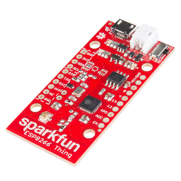
The SparkFun ESP8266 Thing is a breakout and development board for the ESP8266 WiFi SoC – a leading platform for Internet of Things (IoT) or WiFi-related projects. The Thing is low-cost and easy to use, and Arduino IDE integration can be achieved in just a few steps. We've made the ESP8266 easy to use by breaking out all of the module’s pins, adding a LiPo charger, power supply, and all of the other supporting circuitry it requires.
Why the name? We lovingly call it the “Thing” due to it being the perfect foundation for your Internet of Things project. The Thing does everything from turning on an LED to posting data with datastream, and can be programmed just like any microcontroller. You can even program the Thing through the Arduino IDE by installing the ESP8266 Arduino addon.
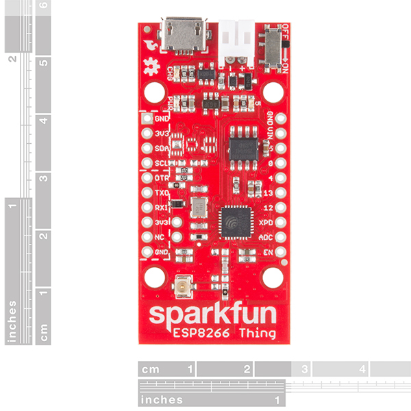
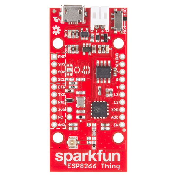
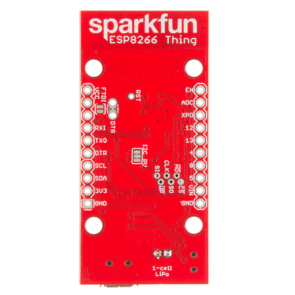
The SparkFun ESP8266 Thing is a relatively simple board. The pins are broken out to two parallel, breadboard-compatible rows. USB and LiPo connectors at the top of the board provide power – controlled by the nearby ON/OFF switch. LEDs towards the inside of the board indicate power, charge, and status of the IC. The ESP8266’s maximum voltage is 3.6V, so the Thing has an onboard 3.3V regulator to deliver a safe, consistent voltage to the IC. That means the ESP8266’s I/O pins also run at 3.3V, you’ll need to level shift any 5V signals running into the IC. A 3.3V FTDI Basic is required to program the SparkFun ESP8266 Thing, but other serial converters with 3.3V I/O levels should work just fine as well. The converter does need a DTR line in addition to the RX and TX pins.
- All module pins broken out
- On-board LiPo charger/power supply
- 802.11 b/g/n
- Wi-Fi Direct (P2P), soft-AP
- Integrated TCP/IP protocol stack
- Integrated TR switch, balun, LNA, power amplifier and matching network
- Integrated PLLs, regulators, DCXO and power management units
- Integrated low power 32-bit CPU could be used as application processor
- +19.5dBm output power in 802.11b mode
SparkFun ESP8266 Thing Product Help and Resources
ESP8266 Powered Propane Poofer
March 15, 2016
Learn how Nick Poole built a WiFi controlled fire-cannon using the ESP8266 Thing Dev Board!
LED Cloud-Connected Cloud
February 22, 2016
Make an RGB colored cloud light! You can also control it from your phone, or hook up to the weather!
LuMini 8x8 Matrix Hookup Guide
January 24, 2019
The LuMini 8x8 Matrix (APA102-2020) are the highest resolution LED matrix available.
Choosing an Arduino for Your Project
December 11, 2017
Examining the diverse world of Arduino boards and understanding the differences between them before choosing one for a project.
Using Flask to Send Data to a Raspberry Pi
November 9, 2017
In this tutorial, we'll show you how to use the Flask framework for Python to send data from ESP8266 WiFi nodes to a Raspberry Pi over an internal WiFi network.
Introduction to MQTT
November 7, 2018
An introduction to MQTT, one of the main communication protocols used with the Internet of Things (IoT).
Internet of Things Experiment Guide
November 23, 2016
The SparkFun ESP8266 Thing Dev Board is a powerful development platform that lets you connect your hardware projects to the Internet. In this guide, we show you how to combine some simple components to remotely log temperature data, send yourself texts and control lights from afar.
ESP8266 Thing Hookup Guide
May 21, 2015
An overview of SparkFun's ESP8266 Thing - a development board for the Internet of...Things. This tutorial explains the circuitry driving the board, and how to get it up and running in an Arduino environment.
Using Home Assistant to Expand Your Home Automations
May 9, 2019
An introduction to Home Assistant, an open source home automation hub.
**No AT command set**
The ESP8266 Thing does not come with the ESP8266 firmware binary for the AT command set like the WiFi Module ESP8266 https://www.sparkfun.com/products/13678. You would need to flash the ESP8266 Thing with the firmware binary to have it recognize the AT commands. As stated this in the comments section as well => https://www.sparkfun.com/products/13231#comment-5571c58bce395fdd058b4567 . To flash the code, there are different tools out there that you could use. Looking at the hookup guide, there are a few links to programs that flash the firmware => https://learn.sparkfun.com/tutorials/esp8266-thing-hookup-guide/resources--going-further .
**Differences "ESP8266 Thing - Dev Board" vs the Original "ESP8266 Thing"?**
This is quite a common question that we get. Looking at the ESP8266 Thing - Dev board , it was designed to keep the cost of the development board low and there were requests to keep the original ESP8266 Thing. The main differences are:
1.) 2-pin JST connector
2.) LiPo charge circuitry
3.) built-in FTDI
4.) Trace for DTR and Debugging
The ESP8266 Thing Dev board does not have the 2-pin JST connector [ https://www.sparkfun.com/products/9749 ] or the LiPo charge circuitry like the original ESP8266 Thing. We have a variety of chargers available on our storefront if you decide that you want to charge the LiPo without removing a LiPo battery from the ESP8266 Dev board => https://www.sparkfun.com/search/results?term=lipo+charger . The LiPoly Charger single cell [ https://www.sparkfun.com/products/12711 ] is more flexible but it is a bit more expensive compared to the other LiPo chargers. This is due to the amount of components that are populated on the board.
The plus side is that there is a built in FTDI on the board to upload code to the board. Personally, I feel that this is a more reliable connection than using the external FTDI basic breakout based on my experience. The ESP8266 Thing Dev board does not include a trace to cut the DTR pin which makes it easier to debug and send serial data to a serial monitor/terminal. You would not need to cut any traces like the original ESP8266 Thing and constantly have to jump the pins when you need to upload.
**Board no longer uploads**
If you had the ESP8266 board compiling and uploading initially in your Arduino IDEs and now it doesn't any more, delete all instances and files related to the ESP8266 in your Arduino15 AppData. On a Windows 7 OS computer, it should look like:
C:\Users\your.username\AppData
Make sure to delete all copies in Local, LocalLow, and Roaming. Then uninstall the board definitions with the board manager, and then reinstall the files.
**Errors when using Mac iOS**
If you see this error output in Arduino v1.6.4 or v1.6.5 and you are using a Mac iOS:
Arduino: 1.6.5 (Mac OS X), Board: "SparkFun ESP8266 Thing, 80 MHz, Serial, 115200"

/Users/.../Library/Arduino15/packages/esp8266/tools/esptool/0.4.6/esptool returned 139
Error compiling.
or if you see this output in Arduino v.1.6.6 and a Mac iOS:
signal: illegal instruction
Error compiling.
The issue is probably due to the ESP8266 board definition and your Mac's iOS version. As soon as we tested this on our older Mac iOS v10.7.5 Lion, we received the same error. Testing this with our engineer's iOS v10.11 EL Capitan, there were no issues compiling. We tried different board definition versions but we were unsuccessful. We even tried deleting the definitions in the “Arduino15” Application Data folder and temporary files. We believe the issue stems from the Mac operating system version and the ESP8266 build => https://github.com/esp8266/Arduino/issues/275#issuecomment-104470653.
Try using the a modified version of the esptool v0.4.6 https://github.com/igrr/esptool-ck/releases that our engineer quickly packaged through our Google Driver => https://drive.google.com/open?id=0B0jwgLkjMWzDWU1pb0RseWdtbmM. Just unzip the files and replace everything in the esptool folder located in your Arduino's App Data folder. The directory will probably be:
/Users/.../Library/Arduino15/packages/
You can also find this through the Arduino IDE and clicking on your preferences.
Otherwise, you would need to update your Mac iOS or wait until there is a fix from the ESP8266 Community.
**Maximum Voltage**
Maximum voltage for the analog ADC pin is 1V, as stated in the hookup guide. You canhook up an analog sensor similar to this => http://www.instructables.com/id/ESP8266-ADC-Analog-Sensors/?ALLSTEPS. For multiple analog sensors, you can try this method http://www.instructables.com/id/ESP8266-with-Multiple-Analog-Sensors/. Or, you could just get an additional analog to digital converter and connect it to the ESP8266 Thing.
Core Skill: Soldering
This skill defines how difficult the soldering is on a particular product. It might be a couple simple solder joints, or require special reflow tools.
Skill Level: Noob - Some basic soldering is required, but it is limited to a just a few pins, basic through-hole soldering, and couple (if any) polarized components. A basic soldering iron is all you should need.
See all skill levels
Core Skill: Programming
If a board needs code or communicates somehow, you're going to need to know how to program or interface with it. The programming skill is all about communication and code.
Skill Level: Competent - The toolchain for programming is a bit more complex and will examples may not be explicitly provided for you. You will be required to have a fundamental knowledge of programming and be required to provide your own code. You may need to modify existing libraries or code to work with your specific hardware. Sensor and hardware interfaces will be SPI or I2C.
See all skill levels
Core Skill: Electrical Prototyping
If it requires power, you need to know how much, what all the pins do, and how to hook it up. You may need to reference datasheets, schematics, and know the ins and outs of electronics.
Skill Level: Rookie - You may be required to know a bit more about the component, such as orientation, or how to hook it up, in addition to power requirements. You will need to understand polarized components.
See all skill levels
Comments
Looking for answers to technical questions?
We welcome your comments and suggestions below. However, if you are looking for solutions to technical questions please see our Technical Assistance page.
Customer Reviews
4.2 out of 5
Based on 49 ratings:
2 of 2 found this helpful:
Very nice way to be introduced to the ESP8266
If you are interested in the ESP8266, I think this is a great way to get into it. The breakout is nice, and gives you access to pretty much everything the 8266 can provide. It's small on flash, smaller than alternatives, but I'm not sure you need much more... they're not so powerful that you'd be using thousands of lines of code. I think in the next rev, it would be nice to have the jumper for GPIO-0 to DTR be a three way jumper, so you pull the jumper off GPIO-0 to DTR and put it back on DTR to XPD for sleep mode... that way you can swap for programming, then swap back for serial debug and sleep mode. I have no use for the Lipo charger, but I am sure others may find that useful. I've used this as my test board, and then use smaller breakout boards for my actual devices I'm building.
4 of 4 found this helpful:
Great product! Documentation could improve.
Got the ESP8266 up & running in short order. Getting it connected & Posting data to my site was the easiest part, particularly with the excellent example code. Minor speed bumps: In Arduino mode, it is a 32-bit processor. Only mention of this is '32-bit CPU' in the Features on the product page. This may (did for me) require some coding changes. Analog input is, indeed on pin 'A0', not '0'. (confused me). And the whole "Serial Monitor" thing was a little confusing - All Arduinos Reset (and go into "boot loader") when you open the Serial Monitor. This just sticks there. Eventually figured everything out, and the information was there. Could use a "Spec" summary page for the Arduino mode - 32 bit, RAM size(?), EEPROM size, Flash size, etc. Again, overall a Great product.
4 of 4 found this helpful:
Best Device Yet for Motion Tracking
I've been working with musicians and dancers for a number of years developing wearable motion tracking devices. We've been through several design iterations including wireless XBee and Bluetooth, both of which had numerous issues (We're using Macs, and Bluetooth is very unreliable under MacOS).
I eventually decided that UDP over WiFi was the best approach to transmitting real-time data at the required rates. While there are such products on the market that target artists, they tend to be quite expensive ($300 and up per unit).
The ESP8266, and especially the ESP8266 Thing have dramatically changed all of that. The ease of programming using the Arduino environment and the power of the 32-bit processor and onboard WiFi, when combined with a 9DOF sensor such as SparkFun's LMS9DS1 IMU, make a great platform for wearable motion tracking.
Added to all that is the fact that the engineers at SparkFun were thoughtful enough to include both an on/off switch (amazing how few devices out there include this---the $300 WiFi unit I mentioned above does not, meaning that you must connect/disconnect the battery from the JST socket every time you use the device, and that requires a tool unless you're willing to break a lot of fingernails) and an on-board charger for the battery (another feature almost universally omitted).
Given the low cost of the ESP8266 Thing and I2C IMU devices, this powerful new platform opens up a lot of new avenues for wearable motion tracking. My only request is that SparkFun take the next step and integrate the 9DOF IMU on the same board as the ESP8266 Thing.
1 of 1 found this helpful:
Great introduction to the ESP8266
This is a great introductory board to the ESP8266 experience. The onboard USB power supply/battery charger and breadboard spacing of the pins really make this a very easy way to begin experimenting with this awesome chip. If you want to improve it, it would be great if there were buttons for reset and programming or pads/traces to add your own. But otherwise, this is an excellent board and I highly recommend it for anyone interested in experimenting with the ESP8266 chip.
Thanks SparkFun!
1 of 1 found this helpful:
A useful, low power, WiFi processor
I use these things to take data in the field and report back via WiFi.
I really like that it has a connector for an external antenna.
I can keep the battery charged with a small 5V solar panel.
However, I really wish there was a pin for VUSB so I didn't have to deal with a USB connector if I didn't want to. It would save a lot of space for me.
While we're at it, if there were pins for on-off as well then I could power switch on the outside of my enclosures.
1 of 1 found this helpful:
amazingly easy
I connected a few I2C temp sensors (TC74) and a non-invasive current sensor to this board and had it sending data over the WiFi network in no time. The Arduino add on rocks - it is great having the libraries available.
The extra features like the USB power connector and pin layout are well worth the extra money over the basic $5 board. This is one of the best examples of great products by the folks at sparkfun.
The Hookup guide was priceless - the examples made it simple to get things rolling without having to scour the internet for resources.
3 of 3 found this helpful:
Don't Forget the SPARKFUN FTDI cable with DTR pinned out!
All in all a pretty good product and fairly easy to use. Remember to get a SPARKFUN FTDI cable with the correct pinout (DTR instead of RTS). My "FTDI cable" purchased from FTDI didn't work. I tried both NodeMCU and Arduino and both work. Note that the NodeMCU GPIO and the ESP8266 Thing GPIO don't line up- there is a conversion table online for this. In general, I like the Arduino approach better since I'm mostly hooking up sensors that already have libraries written for them. Note that you will have to modify some libraries (mainly header includes) for them to be compatible with this MCU. I haven't tested the WiFi range but it works well sitting on my desk. I do wish I had a few more GPIO, but this product is really more for making UI-less sensor nodes than full-blown systems. That said, I still managed to squeeze in a couple of sensors, a display, and pushbuttons with just enough GPIO.
9 of 10 found this helpful:
Nice... Please make a solar version...
This board comes so close to what I want that it's slightly painful that it falls just a little bit short.
The built in 73831 based LiPo charger is a great idea. Having the On-Off switch is less important, IMHO.
The lack of an on-board capacitor to stabilize the input from a Solar Panel is tragic.
Here are the things I'd do to turn this into the perfect Solar development/deployment board:
Put an FTDI chip on it and integrate to the USB connector. Allow power via USB, but don't power the FTDI chip from any of the other power sources (Battery connector). After all, if the USB isn't connected, the FTDI chip isn't going to be doing anything useful.
Replace the 73831 with a 73871. Superior charge controller with battery temperature monitoring and solar optimizations.
Add a Capacitor (or at least space for one), about 4700µf 10v or so to stabilize a solar panel and a place where a 10K NTC thermistor can be added to the board for battery temperature measurement (the 73871 already supports this).
Add small buttons for reset and GPIO0 (closed=ground, open = GPIO0 pulp). This would facilitate flashing. (or better yet, integrate this capability into the FTDI so it can be triggered from the IDE similar to Arduino.
Add a coaxial power plug for attaching the solar cell.
The things I want are going to require some real estate, so let's sacrifice that power switch. I don't think it's all that important in 99% of applications. With the integration of the FTDI, the Serial Programming header pins are nice to have if there's room, but they'd be my second sacrifice.
Finally, that's still probably not going to free up enough real estate, but for most applications, a slightly larger board would be worth the tradeoffs to get these added capabilities.
Thanks for the feedback!
5 of 6 found this helpful:
Simplest and quickest way to get connected to a network/Internet, period!
I tried every single WiFi module out there, and this one is not only the cheapest, but by far the simplest to program and use. I Love the seamless Arduino IDE integration.
More then enough microprocessor power to remote control IoT devices and post data to Phant/ThingSpeak. Had my air quality sensors up and running and posting to ThingSpeak in 20 minutes.
Only shortcoming: Please add FTDI on board.
4 of 6 found this helpful:
Never worked for me
For some reason, I could never get a serial connection to this even by following the guide. I can use the esptool command line utility to report the mac address & other info, but could never flash any new data or send commands.
1 of 2 found this helpful:
Great MQTT Client
Right now, I am using this for a LCD display that monitors an MQTT topic and displays the output. this is handy since I can publish different things like whether the garage door is open or closed, what the current temperature is, and what my unread email account is. MQTT then gives me a very lightweight way to queue up messages and easily read.
super great tool. and because it has its own battery charger, I can charge off of solar and put this out in my back yard and have a visual LCD display showing me what is going on with my MQTT devices at a glance!
0 of 3 found this helpful:
It is a dud!
It is a dud, fortunately ordered similar board from Chinese company for 8$ and works like charm.
Great Hookup Guide. I was laugh-out-loud happy with the web server!
The tutorial is detailed and accurate. The device works well despite slightly flaky programming, even when USB-powered. I hooked up an MPU6050 for a wearable physical therapy aid and it's been very straightforward.
~~~I'd like to know, though: is there a way to store some data and have it survive a spell in deep sleep? I want to record some stats and keep an average that spans several spells in sleep, so I need to record some data while awake and recover it after sleep. Is it possible or should I stick with turning off the radio with WiFi.mode(WIFI_OFF) and accept the higher battery drain?~~~ I believe I need to use system_rtc_mem_write and system_rtc_mem_read
neat board
I use the Arduino IDE with an FTDI 3.3v (DEV-09717) cable on the ESP8266 Thing (non Dev model) for serial monitor functionality, and for programming the device. The 09717 cable is not the best choice for this device, but I made it work.
I do three things to make it work. I run the 5v Vcc from the FTDI cable to a 3.3v regulator on a breadboard, then run the 3.3v to the 3.3v "pin". This is the 3v3 pin between RX1 and NC. The second task is to solder the FTDI jumper, so the 3.3v from the regulator powers the board. The third item is to interrupt the DTR line (green wire) from the FTDI cable at the breadboard. I put a "normally open" pushbutton in that line.
To upload a program to the "Thing", I push and hold the pushbutton, then I click "Upload" in the IDE, then once I see the IDE status message change from "Compiling sketch..." to "Uploading...", I let go of the button. To connect with the serial monitor, just click the serial monitor icon in the IDE, without pushing the pushbutton.
Future feature request: add some sort of analog switch so more than one channel of A to D is available.
Thanks for the tips. Happy hacking!
Great little inexpensive IoT device!
This was amazing easy to get up and running. I followed the hook up guide and program examples and voila, I was up and running and posting data to Phant in almost no time at all. I did have a few hiccups... I never did get the Serial Monitor to work with my Basic FTDI programmer (which made for debugging my code a little more work). But for the price of this "Thing" I'm not worried about it. I set up my board to monitor my garage door so I could check if I leave it open. I included a Dallas Semiconductor I2C temperature chip (just because I wanted to try the I2C bus), a reed relay to sense the door, and stuck a magnet on the garage door frame. I also used the OneWire and Dallas Temperature Control libraries, which made interfacing with the temperature chip a piece of cake. Super easy and it all gets posted to data.sparkfun.com for free, allowing me to check my garage door position and garage temperature from anywhere in the world that I have an internet connection. Eventually, I will add the ability to close my door, but for now I'll just leave it as a position sensor.
0 of 1 found this helpful:
Not very stable
I had a bad experience with these. I purchased two of them and they did not work out very well. They would only program about 10% of the time. Eventually gave up and stopped using them. I will not being buying these again.
Super simple to get up and running.
I had no problems getting this guy up and running following the Hookup Guide. They recommend increasing the upload speed for loading your code onto it but I found that to decrease my success rate and the standard upload speed was not that slow. I have mine posting light sensor data to a phant.io stream and it's been doing great for months now with only a couple drop outs, maybe for a couple hours at a time, and it always reconnects itself. I posted a little more about my experience here: https://katygero.wordpress.com/2016/01/09/iot-light-sensor-its-a-thing/
Its the best thing ever!
This thing makes it very easy to get your thing on the internet. Pretty much tamed the ESP8266 into a simple Arduino programmable board.
The THING
I found it very easy to use. Used the example code and the Arduino addon and had a cell phone interface running in short order.
Great ESP8266 board!
Really like the fast built-in LiPo charger, and the fact that in deep sleep the board will only consume about 70 uA. I only wish it had a bit more flash.
by far the best board to work with!
Extremely easy to setup & get going. It also works just as well with the blynk application for learners looking to experiment with IoT.
Could be better
The Thing does not work with AT commands, in case you are used to the other ESP-xx boards out there. When you hook up a serial terminal, all you get is garbage. To get it working: hook USB power supply, serial to USB converter (3.3V!), CUT the trace on the bottom of the board: when programming from Arduino, have a wire in the two holes to connect the trace, or use a jumper, to run the application, remove the wire or jumper, and power cycle the board. This information is hidden at the end of the tutorial unfortunately, would have save me some time if I had known when I started, I saw quite a few people having this issue. A program and reset button would have been nice, instead of the on/off button
iOT made easy
Used the ESP8266 Thing to interface with sensors and to post data to a MySQL database. Together with the 3.3V FTDI Basic, hook-up, programming and uploading to the Thing could be done very easily; within a day - Thanks to the comprehensive hook-up guide. The only hiccup was the garbled data sent to the serial monitor which was solved by cutting the tracks at the back of the PCB and putting in jumpers for uploading.
Have not connected the USB-serial converter yet!
ESP8266 Thing Dev. This board works fine in two different versions of Linux. Lubuntu 14.04 and Lubuntu 15.01 Please note: The Arduino IDE 1.6.10 does not work correctly in Windows XP. It appears to have a problem with directory paths longer than 255 characters. It took a while but I fixed this problem! Also many of the Wifi examples do not work as advertised. The user should try each one.
Glitchy, but looking forward to v2
The two words that best describe the Thing are "espcomm_open failed". As amazing as this board is, the hit-or-miss process of programming it makes using it a chore. Research into the problem leads me to believe that this is a general issue with the ESP8266, and not a flaw in the design of the Thing, but know that it will definitely affect you.
It was a little confusing when I first powered up the board that I needed to cut traces and add a jumper to make the serial console work, but this was all documented in the hookup guide (with Wifi as the big feature, serial is actually one of the later topics).
In a future revision, it would be nice to have the XPD (deep sleep) pin run over to the header supplied for the DTR/RST connection. This would allow you to move the jumper between DTR/RST for programming and RST/XPD for running.
Simple, Effective, Awesome, Useful
I'm frequently frustrated by the "setup hurdle"; the time it takes to get a new device up and running and doing something useful. The Thing didn't give me any trouble at all. Using Sparkfun's excellent setup guides and example code I was able to create wireless temperature sensors that post data to ThingSpeak (an unrelated but equally awesome cloud data collection service) with only a couple hours of work. The Arduino libraries make it relatively effortless to use, and I had a couple days worth of battery life on a 1,000 mAH lipo while posting a temperature reading every ~5 minutes and deep sleeping between readings. I placed four devices around my house to get an idea of which rooms were warmer than others. A word of warning, however, that although the lipo batteries recommended to power the Thing have all standard protection circuitry, they are completely unprotected from physical damage. My roommate somehow damaged the sensor in his room (probably by stepping on it after he moved it from where I placed it, which wasn't on the floor) causing the bottom of the temp sensor wires I soldered through the board to puncture the thin covering of the battery. Shortly after it caught on fire and was thankfully discovered before it could do any serious damage. I consider myself lucky to only have a hole burned through the carpet and a renter's insurance claim as a result. The Thing is awesome so don't let my battery mishandling experience dissuade you from buying one, I would simply be remiss if I didn't share it in the hopes of preventing at least one similar incident.
Bring the fun
This thing plus Sparkfun's hook up had had me up in running with in a few minutes. I'm starting my temp monitoring system so I can pinpoint rooms that need better HVAC and insulation and to evaluate a better placement of my thermostat. Sparkfun is powering the system.
The corner stone of the project is Phant, their data logging server. The ESP8266 things proved a simple wireless platform for 1-wire sensors. FTDI basic for programming them, and a convenient source for the batteries and sensors.
I got home from work at 8pm. ESP8266 Things came today. I was logging data by 10pm, In that 2 hour span I at dinner, watched TV with the kiddos and conversed with the wife. Oh I read the hook up guide, hacked in some 1 wire code and soldered on some stack-able headers.
Special thanks to spapadim for confirming a replacement memory chip. Looking forward to 8mb of flash.
Update I'm a IPC 7711/7722 repair tech, I hand soldered a TMP102 on 4 of these boards, but I have access to a pretty boss rework station, the tools make the man. I love the spot for a sensor, most people seem to use one at some point. using one that's 60% then a sot23 is more a tease then helpful. That being said, the TMP102's in a bad location for what it is. the chip takes some time to return to ambient (15 minutes or so) after handling, a lot longer after soldering. It's also so sensitive that it detects heat increases if my WIFI signal drops a bit and the processor is on a little longer trying to get a connection. I found this out, because 2 of my Things have very weak antennas, not liking to be out of LOS to the router. I have externals antennas coming so I'll wait and see.
Power LED removal significantly increased uptime. my boards push an update every 63 seconds, giving the boards 3 seconds to connect and push data, and 60 seconds of sleep. On that cycle, 4 days and 29 minutes on a 850mAh battery, average draw is 8 mAh.
Flash upgrade is awesome as well :)
Great Liitle Platform...
This is a great board for IoT applications. The fact that it does have the Li-Po charger on board and the U.FL connector for external antenna is great. The already included I2C pull up resistors is another bonus which although low values have worked in all applications I have used it for.
The only request I would have if this upgraded would be to add more memory to allow OTA updates.
Great product!
Web Product Description Inaccurate
Had to buy Thing Dev to get USB support. Web site should be clearer. I now own both.
Really amazing.
Plenty of support and information. I was up and running really fast.
Works OK, but some problems
The power switch is very flimsy and broke after a couple of weeks. Also, the location of the holes to allow a jumper to be installed/removed from the DTR line is too close to the other holes. When the jumper is in place I can't get the FTDI USB interface to attach to the header without bending things a bit. If the DTR jumper holes were moved inboard a bit it would be better, The documentation was also a bit vague about the XPD-DTR connection for waking up from deep sleep. Once this connection is made you can't get into the bootloader to program the Thing, and that was not mentioned anywhere. Providing holes for a removable jumper for that function would be very nice so I don't have to unsolder a wire to allow for program uploads.
On the plus side, the Arduino add-on works great and the WiFi is easy to use.
Just the ticket for my application!
My application is a kiln temperature monitor. My wife's a ceramic sculpturer and is excited about it. I have all my components playing nice with each other, so it's time to think about an enclosure so I can get it off the breadboard. Really, all she wants to see is the box she can hold in her hand, with a power switch, USB for powering/recharging, and the LCD display.
Couple things have me stymied - the USB and JST battery connector are flush with end of board, so not obvious how to hide the JST/battery inside the enclosure, and the on board power switch is too small and will be inside the enclosure.
I have no experience with SMD devices, but it seems an improvement might be to add a couple of holes for wiring an off-board switch?
Worked as designed but
I used this to create a driveway monitor based on a vibration sensor. It hooked up to my wifi with ease and went for quite a few hours on the small SparkFun LIPO battery I bought with it. The only thing I would like to see added to documentation is a simple example were the Thing acts as a wifi module for an Arduino since the Thing has limited output and I have an application were I shall have to use an Arduino for the heavy sensor work and the Thing just to communicate with my laptop.
Awesome but a minor change would make it even better.
I've been a tinkerer for a long time but haven't had much opportunity the last few decades due to work and family. (Let's just say I'm used to bit banging using assembly on PIC microcontrollers.) Wow, this thing is incredible!
With a solid microcontroller and C programming background but zero experience with Arduino, I've quickly (about two weeks of my spare time) been able to create a leak detector that uses WPS to learn about my WiFi followed by a web UI that allows me to configure other things like hostname, sensor names, SMTP connection info, and FTP connection info. The configuration is stored in flash and once configured it will frequently wake up momentarily to check sensors for leaks with deep sleep inbetween. When water is sensed it will connect to WiFi and send an email letting me know which unit (hostname) and sensor detected the water. This is both to a my email address as well as to an SMS gateway so I also get a text message alerting me. For example, it might say the "kitchen" detected a leak on the "dish washer" sensor. Furthermore, on a daily basis it will update a file on a FTP server that I can monitor with automation on that server to know if the unit ever goes dead (such as the battery is drained) in which case that server will notify me and I can check on the unit and charge the battery. I believe that a 1000mAh battery will last longer than a year between charges. (I've lifted the power LED, etc, to extend batter life.) It's all working perfectly and on such a small unit -- incredible. In all 6 of these will be deployed around my house.
Yes, a different ESP8266 module can be acquired for much less cost but real projects like this will typically be battery powered and those other units may cost less but they don't include an integrated LiPo charger like this unit does. This unit is worth the extra money because of this one board does it all approach. In the end this board, the LiPo battery, a momentary contact push button (for WPS/configuration mode), and wiring harness for the sensor connectors are all being put in a small plastic case along with two light pipes to make the charging LED and the LED on GPIO5 visible outside the enclosure for a nice finished look.
Herein lies the two improvements I can think of. First, I've make the USB port accessible outside the box and it does work but it would be nice if the USB port hung off the board just a bit more for some mechanical margin; an extra 1/16" would be nice but even 1/32" would help. Second, the battery is inside the case so having the plug face out on the same side as the USB is really useless. I've resorted to soldering the battery leads to the board but if the board were laid out differently, perhaps with the USB connector moved to where the battery plug currently is and the battery plug moved to the side opposite the power switch, this board would be even better as that would allow the battery to use the plug and be inside the enclosure. (This is the only reason for 4 stars instead of 5.)
Good learning experience
I bought this wanting to learn about micropython on 8266. That was a bust because I could not find a micropython build that would load on this particular board. However, I switched to learning how to program this board using VSCode with the platformIO plugin and C++ and indeed I have learned a ton of stuff about making that all work. Very fun getting this little thing to show up on my network and post data to ThingSpeak.com.
Super easy to get started
It was very easy to get this up and running.
Great little Thing
I've spent more time than is probably wise with the Thing this week, really like it. (Using it for a touchscreen WiFi clock + bedside controller for Magic-Home WiFi lights -- kind of a DIY Chumby, if anyone remembers those)
My only "complaint" is that the flash is not large enough do to OTA (over-the-air) updates: this requires at least 1MByte flash (sketch update is saved in free space, and copied over upon reboot). I can confirm that replacing the 4Mbit (512Kbyte) flash chip with it's 8Mbit version (Adesto AT25SF08) works, with no other changes required (other than boards.txt, if you're using Arduino). In particular, first-stage bootloader is burned into ESP ROM (so you don't need any SOIC programming fixtures etc; very easy replacement). Hopefully SparkFun will eventually update the Thing, so OTA updates work out of the box.
Other than that, great board and I have a few suggestions that are different from what other ppl may have suggested, and like it more the way it is now.
One quick minor feedback: the JST header placement is a little unfortunate. I want to put it in a 3D printed case, with USB exposed, so the JST would hit the enclosure's wall. I had to de-solder it and solder a vertical JST header instead.
So, things to consider: (i) don't populate the JST, include unsoldered header as option; (ii) make it face another side of the PCB (not same as USB; maybe move power switch to opposite side and rotate JST 90deg?); (iii) inset it into PCB, leaving space for the male connector and wires.
As for power switch: given that the Thing has a battery, and unplugging USB won't power it down if a LiPo is inserted, I would not remove it (as someone suggested). Too much hassle unplugging/replugging JST (plus, if ppl want to solder battery directly, then it'd be impossible to power off).
And a final tip I found useful: for DTR, I just cut my FTDI cable's DTR wire, and crimped a M/F pin pair, so I can easily cut the connection. Much easier on fingers than fiddling with a tiny jumper next to the pin header. Now I just leave the serial monitor open, plug pin headers together before starting upload, and just quickly pull the pin headers apart as soon as I see esptool start flashing. Maybe an inline switch would be even better, but this is quick and easy enough.
So, if you do add FTDI on board (I prefer not, but that's just me), I'd be a little upset if the tiny jumper was the only way to break the DTR connection. :) But, please, don't go the RESET + PROGRAM pushbutton pair route (I have it on an Adafruit breakout and, while I like that too, flashing it is a major PITA, so I always go for the Thing instead).
Works great overall, thanks! Now, if you'll excuse me, I'll go back to ripping my hair out with I2C reads on Arduino for the ESP... :)
Great product
Like most things from Sparkfun, it's a well-engineered product that works as advertised. There is a lot of similarity and code swapping capability between The Thing, the Ada fruit Huzzah and the Photon, but the lipo battery connector and charging circuit is a unique addition....ands is the space for a couple of other ic's. Well done SF!
Really enjoying the Thing
Took me a while to get going with programming it using the Arduino IDE (and I'm still not 100% on what the deal was) but I've got it playing nice and logging to data.sparkfun.com now.
Quick question, though: Is there any discharge protection on the LiPo path to keep this from over draining the battery? I'm not in a position to test it since I accidentally shorted Vin and Gnd pins while it was plugged into my computer via USB...
All of our silver single cell lipos have built in protection circuits. Additionally this board has the MCP73831 which does power management and circuit protection for the battery. You should be all good to let your battery go unattended without damage.
Great Starter for IOT
Finally got my Thing up and running. As a novice to Arduino, setting up and using the environment went well until I tried to post to the Phant. Needed to backup and figure out how to install the libraries for that. (Isn't mentioned in the Tutorial) But after that it connected up and functions beautifully.
Excellent!
- Straightforward breakout.
- Easy serial connection/programming.
- Very handy library for the "Arduino" IDE.
- All examples from the "Hookup Guide" worked right away.
Combined with a MUX is a good measurement station.
If you want something working right out of the shelf, without headache - that's you Thing.
Nice collection of capabilities
I am running an Internet-of-Things special interest group for our local makerspace. I purchased a few of these along with a bunch of other devices (Particle Photon, NodeMCU Dev v0.9 boards, ESP8266 boards, etc.). After some initial issues with finding an FTDI board that would work, it was very easy to put up a sketch to upload DHT22 temp/humidity data to ThinkSpeak. Much more reliable and stable than the NodeMCU stuff. I will be buying some more as we expand our project ... definitely want to make some "Cloud Clouds"!
Great board but not clear how it differentiates from Huzzah
Easy to program, I've got my chicken-door open/closed sensor (almost) up and running. https://github.com/Sequoia/cluck/blob/gh-pages/thing_door_phant_sleep.ino
What would make it perfect for me:
- Make it a liiitle skinnier so it can be used on a standard small breadboard more easily. Currently it covers all but the outermost row & those rows are partly covered.
- add either a jumper connection or a (ideally) a spot to add a switch (like on/off switch) to connect XPD to DTR/RST. I use deepSleep in my sketch & debugging/reprogramming requires switching that connection off & on each time.
Other things I desire
- Fritzing part!!
- Info in "powering the thing" on powering with solar (seems like a very common use-case)
Overall I like it & I have recommended it to friends but I'll probably try the Huzzah next time simply because the price is lower & if you're comfortable soldering a JST connector it's not clear (to me) how The Thing is worth 60% more than the Huzzah. Basically, I like it but there's something cheaper that seems to do the same thing!
UPDATE: tutorial to address EXACTLY what I am trying to do (power Thing on solar power) yey! :) https://www.hackster.io/fablabeu/esp8266-thing-by-sparkfun-982bc6
UPDATE 2: I spoke too soon, I actually can't easily follow that tutorial (need a bit more hand-holding I guess). Oh well, it's a start!
0 of 1 found this helpful:
works great.. Just got two more
I made an rgb led cloud for my sons room controlled via the blynk app. It works great for IOT projects. Really easy to program and hook up.
-------------------- Tech Support Tips/Troubleshooting/Common Issues --------------------
Differences "ESP8266 Thing - Dev Board" vs the Original "ESP8266 Thing"?
This is quite a common question that we get. Looking at the ESP8266 Thing - Dev board , it was designed to keep the cost of the development board low and there were requests to keep the original ESP8266 Thing. The main differences are:
The ESP8266 Thing Dev board does not have the 2-pin JST connector [ https://www.sparkfun.com/products/9749 ] or the LiPo charge circuitry like the original ESP8266 Thing. We have a variety of chargers available on our storefront if you decide that you want to charge the LiPo without removing a LiPo battery from the ESP8266 Dev board => https://www.sparkfun.com/search/results?term=lipo+charger . The LiPoly Charger single cell [ https://www.sparkfun.com/products/12711 ] is more flexible but it is a bit more expensive compared to the other LiPo chargers. This is due to the amount of components that are populated on the board.
The plus side is that there is a built in FTDI on the board to upload code to the board. Personally, I feel that this is a more reliable connection than using the external FTDI basic breakout based on my experience. The ESP8266 Thing Dev board does not include a trace to cut the DTR pin which makes it easier to debug and send serial data to a serial monitor/terminal. You would not need to cut any traces like the original ESP8266 Thing and constantly have to jump the pins when you need to upload.
Upload Error Issues
If you are seeing this error using the Thing:
flip the power switch to OFF, press the upload button on Arduino with the correct settings for the Thing, and flip the power switch back to ON right before upload. You have to get the timing right in order to upload code.
Try looking at this other comment thread for other troubleshooting tips with that error => https://learn.sparkfun.com/tutorials/esp8266-thing-hookup-guide/discuss#comment-55a05571ce395f88538b4567 .
I had some success by cranking the baud rate all the way up. Almost as if I was trying to beat a WDT reset. I'll try the stuff above on my next one if it causes issues. So far 2 of 3 are doing it. One works fine all the time.
******Update******* Got bit by a fake FTDI chip. I had ordered some 3.3/5v usb to serials on Amazon for a good price. It actually cost me 4 days of my time fighting and researching to figure out what was wrong. I had 2 of them so when I tried cables and power supplies and even a second board, I thought it had to be the Thing. Then I found I had grabbed an RFD22121 usb to serial adapter. So I rigged it to the thing. The only problem was it apparently doesn't pull down DTR, so then I hooked the fake ftdi to the DTR on the thing, opened putty on a second com port, the Thing dropped right into download mode and took sketch after sketch. Amazing. Sometimes saving a few bucks isn't worth it.
Another way around this issue I found was to
Remove C6
Remove D5 and replaced it with a short.
When I need to program I just hold down DTR to ground and power cycle the thing, Program the thing and remove DTR from ground. Easy. Never had an issue since. I have a funny feeling something funny is happening with the DTR and reset on programming.....
I was just working on my project with an ESP8266 Thing and a photo transistor. I seem to have triggered something by accident. Both the power and the charge LEDs are on, solid, when I plug in the board and the power switch is set to the on position. Additionally I can no longer upload sketches. When I connect the serial basic to program, the RX light stays on. The fact that it wasn't fixed by unplugging it makes me very concerned.
Anyone know what I might have done, or how I can fix it? Did I brick this Thing somehow?
Is it possible to hook-up an external power switch? For instance if I want to mount the board in a case and want to switch the power on/off without opening the case.
Yes. Here are some guides on the basics of electronics, that we have written, which will help you with that:
Thanks for the response, although my question was related to the esp thing specifically. Where can I connect the two ends of the switch onto the board? I do not see any connectors nor PTH's for an external switch. Other than unsoldering the currently embedded switch and soldering an external switch to it, I don't see an easy solution.
So, it sounds like you are looking for technical assistance. Please use the link in the banner above, to get started with posting a topic in our forums. Our technical support team will do their best to assist you.
That being said, if you take a look at the example in the Switch Basics tutorial, you should be able to get a good idea of how to use a switch to cut power to the board. To be more specific, you should be attaching the switch to your power supply (into the board) and not the board itself. (If you look at the schematics for the ESP8266 Thing, there are no breakout pins on the board to attach a power switch.)
I don't know if everyone already knew this, but here it is:
I was having a lot of trouble trying to run this off of battery, whether the LiPo's that are sold as accessories, or a 3 AA holder at 4.5 V to the Vin Pin, or a 6V battery run through a 5V voltage regulator to the Vin pin. After over an hour of trying different things and getting only gibberish in the serial monitor, I decided to disconnect the FTDI cable and try my battery power options. All 3 work with the serial header disconnected. So, for development and debugging, run your ESP8266 off USB power, which works fine with the FTDI cable connected, then work off your power selection in deployment.
If there is something I am missing about this, I'd love to hear a suggestion. I need to power an H-bridge at 6V, so I thought a voltage regulator off that main supply could power the Vin pin on the Thing, since the Vin range on the spec sheet is 3.3 - 5.5.V.
So for now, while I work on my code, I'll power the H-bridge only off the 6V and the Thing from the USB micro connection. I can't wait to get this all pulled together. Now that I have learned some off the tricks to using this Thing, I already have a few other ideas for it.
I put a tiny version of MicroPython on this module but I couldn't get many features working, not sure if it was due to being stripped down to reduce the size of the BIN or simply that MicroPython wont run on this module. I want to revert back to the default firmware, can I download it or is it possible to force a reset on the board to get back to factory fresh? Thanks, Jason
hi, is it possible to program the sparkfun esp8266 thing with this usb to ttl adapter without dtr port?
Probably, you may have to manually reset the board at the correct time (which can be tricky to figure out), but it should work in theory.
Info on simple $3.35 "proto shield" for devel work at bottom of... http://sheepdogguides.com/elec/misc/esp8266/esp8266-main.htm (Along with comments on this Things cousin, the Thing, Dev Board.)
Does the battery charging circuit have a way of getting the current battery level similar to the Qduino Mini?
how secure is the web control to this device? I what to no if this would be secure enough to be a internet device that could be connected to two office servers to connect to there power switch, reset switch, power led & hdd led?
I have two in house servers that we need to be able to shut down when lighting storms are approaching then boot back up after they have passed. Also sometimes the servers locks up and we need to reboot them to get them back going. Note we have remote access to these systems but if it locked up or crash running the remote software and no one is at the office at 2 am, this should give us the ability to reboot them independent of the OS.
We need to make sure it has secure access to this board so just not anyone can shut down or reset these systems.
Is it possible to toggle a relay with this? Like the SparkFun Beefcake Relay or maybe the PowerSwitch Tail II?
I got the Thing up and running to the point it was serving web pages and I could download them from another PC on my network. Now the Thing has stopped working. The Charge and Power lights are stuck on permanently and the serial port prints out "ets Jan 8 2" and some garbage ascii. Is there a way to reset this or did something break?
Has anyone had success with ESP8266 Basic http://www.esp8266basic.com/ on this board?
I keep getting these errors: Failed Wifi Connect file open failed
I flashed ESP Basic 1.89, using esptool.py and the FTDI Basic 3.3.
Love this video
Does anyone have an idea about how to send the SSID and password to the board from an app/mobile/client using Soft AP? Thanks!
It seems to me that the battery connector is wired up backwards to convention. I plugged one of my 500 maH single cell helicopter batteries into it (Blade Glimpse) and it smoked Q1. I should have checked the polarity beforehand but I assumed that all JST pinouts were the same.
The Thing still works off of USB and the battery charger chip seems to have survived (it is putting out 4.3V to the battery connector) but the FET is a goner. I cannot read the part number (burned through) - what is an appropriate replacement FET in case I want to try it again?
Shoot. Sorry about that! The battery connector polarity matches our LiPo batteries with the mating JST connector.
That MOSFET is a DMG2307L in a SOT23 package.
I have a question of this board. Whats the point of C8 in the antenna routing (5.6pF) does it make the work of a balun?
I can't get the serial monitor not to display griberish, although I followed the directions to cut the trace of the DTR jumper. With or without the jumper, i get only griberish which as a result makes the use of AT commands impossible with this board. I do not advise people to buy this board if you need to have access to AT commands. it works only with uploading sketches which is very disappointing and frustrating for an ESP8266 board that is twice the price of a standard module (on which by the way i have very easily access to AT commands on serial monitor).
The "ESP8266 Thing Hookup Guide" has a bug in the download version of "ESP8266_SoftAP_Server.ino"
On line 101 of the download version of "ESP8266_SoftAP_Server.ino", the memset() call is incorrect, leaving garbage chars in the AP_NameChar string. It is correct in the code shown on the webpage Example Sketch: AP Web Server.
Dan
What's the difference between this Thing and the Thing Dev Board? I can't easily tell, it looks like the dev board doesn't have a battery connector populated?
The Dev board has an on-board FTDI chip. This Thing requires a separate FTDI breakout for programming. Also, due to the extra board space, this Thing has footprints for a few different sensors that could be added on by the user.
I have created a video tutorial for this part: http://thesignalpath.com/blogs/2015/12/07/tutorial-and-experiments-with-esp8266-soc-blynk-app-arduino-and-internet-of-things-iot/
Will this thing cut off at 2.8V to protect the battery from over-discharge? Looking at the schematic it looks like it can go as low as 1.7V which will certainly damage the lipo and in some cases might even cause fire. It would be nice to have such a feature on board since you went to the trouble to add the charging chip, etc.
Can you at Sparkfun pleas make a Fritzing part for this module? I used it in this project http://www.thingiverse.com/thing:1135404 and a lot off people asks for the wiring diagram for the project ;-)
Does it have a watchdog? Is it possible to make posts to a server?
What kind of battery could I use with the ESP8266? And how long would it last?
I would like to see an option with the FTDI on board. I was excited when I saw the USB connector, but then disappointed when I looked at the schematic.
Yeah, the NodeMCU clone boards have it built on.
I actually had one in my hand when I was writing that post. It would be nice to have something sourced in the country though. I am aware that the chip might come from overseas, but sometimes the production quality of stuff from eBay (China) is not up to snuff or does not work at all.
Love this Thing. We made a super simple IoT sensor for baking bread with it, parts list and code included: https://github.com/bwhitman/bread-detector
great Thing ... I just modified it a bit to power it solely by solar power check it out: https://www.hackster.io/fablabeu/esp8266-thing-by-sparkfun second, while I had initial "no memory" problems with the I2C (BMP180) I put my findings here https://www.hackster.io/fablabeu/esp8266-sensor - hope this is of value to the community ;-)
Why gpio 16 is marked as Xpo?
GPIO16's alternate name is "XPD_DCDC." It's used to wake the ESP8266 up after deep sleep, as documented here.
Hi, I attempted to install the ESP8266 Arduino addon as instructed in the hookup guide but received the following error: "https://raw.githubusercontent.com/sparkfun/Arduino_Boards/esp8266/IDE_Board_Manager/package_sparkfun_index.json file signature verification failed. File ignored." This error occurs when I open the board manager. I was able to successfully install a different addon as described at https://github.com/esp8266/arduino. This addon installed without incident, however it is unclear whether the Thing can be programmed using any of these modules. Has anyone successfully installed the Sparkfun ESP8266 Thing addon as described in the hookup guide? If not, can any of the modules provided by the ESP8266 Arduino github can be used to program the Thing?
Thanks.
Dito: arduino-1.6.4 on linux (ubuntu 14.04LTS)
Weird. We'll look into this more - it's worked for me on a few platforms (Mac and Windows 7,8), but hasn't been exhaustively tested.
If you've got the esp8266/arduino addon, select "Generic ESP8266 Module" as the board, then set the flash size to "4M", and that should work for the Thing.
Does this setting need to happen with "Sparkfun Thing" as the board? I can't for the life of me get the thing flashed with ubuntu 15.04. I suspect that it's a esptool issue. I even tried 0.4.5 with no success. I've reported the issue in upstream esptool-ck here: https://github.com/igrr/esptool-ck/issues/1#issuecomment-109005481
Using the Sparkfun FTDI basic breakout 3.3V.
Thanks, I was able to program the Thing using the settings you recommended. The error occurred on Ubuntu 14.04 with Arduino 1.6.4 for me as well.
ESP indeed! I was just thinking when I saw the module, that a better board was needed. Something like the Pro Mini but based on the ESP8266. You must have read my mind. I especially like that you included the LiPo charger. This is just about perfect for a simple IoT solution.
Except I would have named it "Io". Then the shield-like boards that supply the Thing specific functions (sensors and such) could be "T"s. ;-)
Good job folks!
Couldn't wait. "Shield" proto board design: https://forum.sparkfun.com/viewtopic.php?f=42&t=41147
What about the ESP features? How can I be like Professor X?
What's the max current that can be drawn from the VIN pin ? For instance could I power a cheap servo when the board is plugged on USB ?
What about PWM ? There's no mention of it anywhere, but there's a PWM LED tutorial in the book, si I guess every GPIO do ?
Thanks in advance
The max current will mostly depend on your power source. If you're using USB, you can probably expect around 500mA (minus a little bit for whatever the ESP8266 is pulling).
If you're using a battery, the supply capacity will vary, but you should be able to get enough out of most LiPo's to drive servo. If you're battery doesn't have a lower limit, the Q1 MOSFET may end up limiting the current to around 2.5A.
And, yes, every GPIO has PWM-capabilities -- assuming your using the Arduino addon.
Is it possible to attach a serial RFID reader to the RX/TX pins of the Thing and use these in the code for example to post the key to an URL?
I am having the toughest time trying to get my ESP8266 Thing to connect to my wifi network. I can easily create a wifi hotspot with it. but, I cant connect to any of my wifi routers (I have tried several)
It seems to get stuck here: while (WiFi.status() != WL_CONNECTED)
Are there any limitations to types of wife security I can connect to?
NOTE: I figured out my problem. the SSID is case sensitive. I feel stupid after spending 2 days pouting about this :)
How much flash does this board have ? is it 4Mb ?
Yup, 4Mb (512KB).
Hi, Got it working with example sketches very easy. However I am trying to get a I2C alphanumeric display working with example sketch with no avail...... (https://github.com/adafruit/Adafruit-LED-Backpack-Library/blob/master/examples/quadalphanum/quadalphanum.ino)
Is there some special I2C setup I may be missing that should be included in the above example? Any help much appreciated.
Will
Just a follow up on this, To fix my problem.
I removed C6 completely.
I removed D5 and replaced it with a short.
When I need to program I just hold down DTR to ground and power cycle the thing, Program the thing and remove DTR from ground.
Easy. Never had an issue since.
I have a funny feeling something funny is happening with the DTR and reset on programming.....
Will
Do you plan on offering this with 8 Mbit of SPI flash instead of 4 Mbit? This will help enable the CIUPDATE command in the latest SDK.
Originally posted a comment about wall wart difficulty. Have recently discovered that my unit was manufactured with the u.FL mounted "backward" - the center pin is connected to the "NC" pad instead of the signal input. Turns out that not having an antenna connected causes BAD things to happen, like processor resets when trying to access WiFi. Check the continuity if you're planning on using the u.FL connector.
Found out after some frustration to get Onewire working you need to get the modified onewire.h file off the esp8266 arduino github respository (https://github.com/esp8266/Arduino). While sparkfun has setup a nice repository for the thing board itself might also be useful to add a bit to the hookup guide about getting the other libraries for esp8266. But now I got everything working great and have a remote temperature sensor for the pool.
I've got a few of these now and love them. Watch the DTR line if you're programming and want to use Serial for debug.
I've not been able to connect one acting as a client to another acting as an AP/server. Is there a limitation that prevents this? Has anyone done it?
I cannot get the Arduino serialEvent() to fire. Was this implemented for SparkFun ESP8266 Thing?
What do I do with the DTR and VCC lines when using the sparkfun FTDI cable? I am continuously getting the espcomm_sync failed errors/warnings.
Is there a way to program this with Sparkfun's RS232 shifter https://www.sparkfun.com/products/449 ? There isn't a DTR pin and I don't have an FTDI basic handy. Thanks.
It'll require some manual wiring, and on/off switching, but it's possible.
To get the ESP8266 into bootloader mode, GPIO0 needs to be low, but to run a program GPIO0 needs to be high. So you'll need a jumper wire that you can easily connect/disconnect. Wire GPIO0 to GND if you're programming, leave the pin floating (there's an on-board pull-up resistor) if you want to run its program.
After you've wired GPIO0 to GND, reset the ESP8266 by sliding the on/off switch off then on. It should now be in bootloader mode, and you should be able to upload a sketch to it with just GND, RX, and TX wired up from your RS232 Shifter.
Thanks for your response. I tried what you recommended though I can't stop getting the espcomm_sync failed and espcomm_open failed messages. I've tried the turning it off then back on right before upload method.. Any other suggestions? Also, shouldn't I connect the 3.3V to the shifter? Thanks!
What I'd really rather like is one of these with a regulator that can take a really wide range of input voltages - say, up to 36V. Which is to say, an esp8266 module with a few GPIO pins that can share a power input with a pico/femtobuck without having to have a separate regulator.
Really? 36V, what micro-controller board can handle that much on it's own?
Hello everyone,
I have a quick question, I am looking to purchase this over the WRL-13252 simply because it has an external antenna connector. Now, I was wondering, once I install the AT command firmware, will this product have the same functionality as the WRL-13252? Or will I need to make additional configurations? As in will it function as a serial -> wireless (and vice versa) device? I am looking to control my microcontroller with my laptop via wirelessly. I will be setting and querying variables.
Can the LiPo be attached as a backup power source for situations where the USB power source fails??
So, I have both a LiPo and USB walwart plugged into the unit, the power will draw from the USB and charge the LiPo. Then the USB power goes out because of a storm. Does the power automatically shift to the LiPo?
Yes, if both USB and LiPo are connected, the Thing will power off the USB (and some of the USB power will be used to charge the LiPo).
If, for whatever reason, USB power goes away, the board will automatically switch to LiPo supply -- and the ESP8266 shouldn't reset.
So.. after reading all the comments I realize there is none greener than I on this board... so please bear with me.. I love this Thing!! It will turn a led on and off and it will post to phant...the sparkfun tutorials Rock.. I actually programed my thing in under 3 hours (including updating arduino ide and installing stuff) it was awesome. So here are my questions. 1. I can freely use digital inputs and outputs 5,0,4,13,12 as well as 2,4 (assuming no i2c spi use...)
as well as the 1 volt limitedA0 pin? 2. The led pin on/off software rocks.. however i noticed it only works if im on the same network...How do I set it so that it will work from my work (or for that matter any remote) computer? Im assuming the "Posting to phant" combined with the Ap web server example of led on/off will allow one to do this.. and by one I not me... I tried mixing and matching the statement into the code but could never get it to compile... ideas?
I don't know if you already tried this, but you would need to port forward the local server to your public ip.
Anyone else have issues with the ADC not reading right? According to all my research, if the unit is transmitting, it will give erroneous data on the ADC... I'm looking for numbers in the 50s, and it spikes 50% - 75% of the time to 430 of 1023. My research also tells me the radio transmit will goof the ADC cause it's used for something during transmit, so if you want to use the ADC you must put the radio in modem sleep mode... but that mode doesn't seem available in the arduino environment. Been able to get everything else working great with the hookup guide, but this one is driving me nuts.
Hmm, I must say I am rather disappointed that there is no button on GPIO0 for programming and that the I2C sensors are not populated, despite being included on the schematic. I keep getting the dreaded warning: espcomm_sync failed error: espcomm_open failed failures
How do you set the time/date? I successfully setup a data stream on data.sparkfun.com and having posting data ever 5 minutes. The date/time stamp is all wrong. Are there commands or code to set the time/date after the Thing is powered up?
The time/date stamp on data.sparkfun.com are all set to UTC, and that can't be modified. You can get a timezone converted output by adding a
timezone=IANA_TIME_ZONEto the end of your output request (whereIANA_TIME_ZONEis a value from this list. For example: https://data.sparkfun.com/output/wpvZ9pE1qbFJAjaGd3bn?timezone=America/Denver.Looking over the board and the schematics it doesn't look like GPIO15 is brought anywhere. It is tied to ground via a 10K resister but doesn't appear on any of the headers. Am I missing something?
Thanks!
Is anyone else having trouble with the sqrt(), log() and exp() functions in the Arduino environment? I tried to build a small capacitance meter with the Thing but when I use any of the above calls the ESP reboots. It appears as if there is a loop that takes too long to complete inside the these functions and the watchdog timer kicks the board out of the loop(). Any idea where/how to look into this?
Ok found the problem for the bad ADC reading. It was a bad joint ! Now it works very well.
Sorry for the unecessary post.
Alberto
I uploaded to the "Thing" the example sketch "AP Web Server" with success. I can read and write but the ADC does not work! It just shows reading from 30 to 60 where I was expecting a reading of 307 ( with 0,3 volts applied). Is the code or the esp ADC does not work properly?
Alberto
Which baud rate should I use for the "Thing" I did try with 115200 (the baud rate I used with the wifi module) but nothing happens. My intention is to begin using the "Thing" with the AT commands I did use with the wifi module. Is it possible ? (I cut the DTR short)
Thank you for the answer. Alberto
It should support most standard baud rates, including 115200. But the Thing does not come flashed with the AT command firmware, so maybe that's why you're not getting a response. You'd need to program that firmware onto it. You can download Espressif's official AT firmware here, or you may want to check out the community's improved AT command firmware in this forum.
Thank you Jimb0 for the quick answer. So I cannot use gpio16 as a digital IO ? Or if I will not use the sleep, then I could use it ?
Sorry for the simple questions but I just started and I have a long way to go before I could use this item properly.
Alberto
If you don't need the wake-from-sleep functionality, you can definitely use GPIO16 as a digital I/O. If you're using the Arduino IDE, just write/read to pin 16.
How much Flash RAM has this board? The latest versions of the Espressif SDK required a minimum of 8mbit Flash onboard.
Do I need to buy an antenna? If so, what is recommended?
You shouldn't need an antenna, the PCB includes a trace antenna. Connecting a U.FL antenna (like this one) is optional, and requires modification of the PCB. See this section of the hookup guide for more info.
Can't wait to try out the Thing I just ordered.
The two issues I've run into are so far are:
Thanks for any help.
The ATECC108 pad seems to be a UDFN, correct? if so any chance of a batch having a SOIC pad? Then again there doesn't seem to be a public full datasheet for the ATECC108, given that it's ASFAIK a superset of the ATSH204(A), so would a ATSHA204 work just as well?
Just ordered the Thing from Sparkfun along with a 850mA lipo battery. Is it possible to connect the large solarpanel from sparkfun(5W) directly to the power input and let it charge the lipo during daytime and pull power from the lipo during nighttime? Or do i need a separate solarcharger circuit as well?
To charge efficiently, you'll want to get/build a solar powering circuit.
It's a reasonable idea; unfortunately the maximum voltage the MCP73831 Lipo charger can take is 7.0V, which could be exceeded by the large solar panel. There are various tricks you could try to get it to work (use the smaller panel, use a zener shunt on the large panel), or you could use a Sunny Buddy solar charger instead.
But if I have a small panel this should work correct?
Hello!
Can you provide separate LiPo battery management module? Those part that titled as "Voltage Regulator & LiPo Charger" on the Schematic.
I already have some ESP modules but want to use them with LiPo. And a small module which will handle all the LiPo management (charging, converting to 3.3V, checking left capacity and other) will be very nice to have!
Thanks!
The PowerCell is pretty close to that circuit. It charges and regulates a LiPo battery to produce a 3.3V out. If you need to monitor the voltage/charge, check out the LiPo Fuel Gauge.
do this board conform to FCC regulation.?
This board is not in conflict with any FCC regulations, but it is not FCC certified.
Ah, that is to bad, as it is hard to find FCC certified. boards. and our customer is unlikely to accept things with non FCC certified.wireless parts.
There are FCC Certified ESP8266 modules you can buy. The Adafruit Huzzah board has one mounted atop a board with custom circuitry. I'm not familiar with FCC regulations so I"m not sure if their board would fit your needs but the module itself they use is certified. Sadly the module doesn't breakout all of the functionality of the ESP8266 but it does provide more than the 8-pin modules.
FTDI on board would be nice if you can do it at this price-point, but you've got the pin-out in the right order on the side so it's easy enough to connect the FTDI Basic- good thinking.
Yeah, FTDI is one of those things that is nice, but would add $5-10 to the board. Since you probably are only going to need it once or twice we figure we'd leave it off and let you use your own.
ESP8266.com, https://github.com/esp8266/arduino, https://github.com/nodemcu/nodemcu-firmware and tons of other info out there.
A sweet tutorial would be an example of how to use the SoftAP (?) capability to allow the Thing to bring up a web service and allow a user to enter a SSID and password (if required) and then have the Thing attach to that WiFi network and push data via it. I know this has been done via NodeMCU, but I don't know if it's possible via the Arduino IDE. A challenge may be how to store the credentials for reboots.
I agree, all these IoT boards that are coming out from different vendors; none of them are the complete solution. This one from SparkFun comes close but it is only missing two things: 1. A EEPROM where you can store the SSID and Password. 2. Means to update the firmware over the air.
By default it reconnects to the last AP you were connected to on power-up. That's why in the examples one of the setup lines is wifi.disconnect();
https://github.com/esp8266/arduino to program via Arduino IDE.