SparkFun RGB LED Breakout - WS2812B
BOB-13282

SparkFun RGB LED Breakout - WS2812B
SKU: BOB-13282
$4.95
In stock
SKU
BOB-13282
Helpful Documentation
 Hookup Guide
 Schematic
 Datasheet (WS2812B)
Product Overview
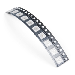
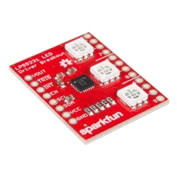
This is a breakout board for the WS2812B RGB LED. The WS2812B is actually an RGB LED with a WS2811 built right into the LED! All the necessary pins are broken out to 0.1" spaced headers for easy bread-boarding. Several of these breakouts can even be chained together to form a display or an addressable string.
Documents:
- Schematic
- Eagle Files
- Hookup Guide
- Datasheet (WS2812B)
- GitHub (Design Files & Example Code)
Similar Items
-
-
-
-
 SMD LED - RGB APA102C-5050 (Pack of 10)
Special Price Current price: $3.15 Regular Price Original price: $4.50Discontinued
SMD LED - RGB APA102C-5050 (Pack of 10)
Special Price Current price: $3.15 Regular Price Original price: $4.50Discontinued -
-
-


Hookup Accessories


Documentation
- Schematic
- Eagle Files
- Hookup Guide
- All About LEDs
- Datasheet (WS2812B)
- GitHub (Design Files & Example Code)
Customer Reviews

SparkFun RGB LED Breakout - WS2812B
$4.95
BOB-13282
Stock and Customer Discounts
$4.95 retail price.
Available Discounts
- $4.70 | 10+ units
- $4.46 | 25+ units
- $4.21 | 100+ units