SparkFun Beefcake Relay Control Kit (Ver. 2.0)
Product Overview
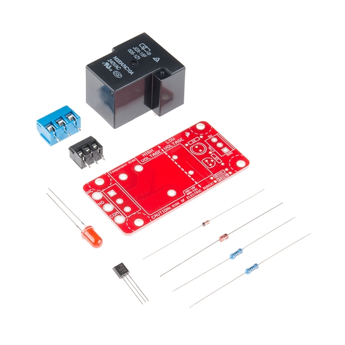
Your 5V system can wield great power with this big, beefy relay board. How does 10A on the NC contacts and 20A on the NO contacts at 220VAC sound? The SparkFun Beefcake Relay Control Kit contains all the parts you need to get your high-power load under control. Only minimal assembly is required!
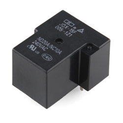
The heart of the board is a sealed, SPDT 20A/10A Relay. The relay is controlled by 5V logic through a transistor, and an LED tells you when the relay is closed. This is a kit, so it comes as through-hole parts with assembly required, which makes for some nice soldering practice. Screw terminal connectors on either side of the board make it easy to incorporate into your project.
There are some pretty beefy traces connecting the relay to the load pins, but the 3-pin terminals are only rated for 15A max! If you plan on connecting a larger load, you'll need to solder directly to the board. As always with high current and voltage, play it safe and use your judgment when deciding how much of a load you want to put on a board -- in open airflow the PCB can handle the full 20A for a few minutes at a time, but in an enclosed area heat can build up.
Note: Please keep in mind that this board is really meant for someone with experience and good knowledge of electricity. If you're uncomfortable soldering or dealing with high voltage, please check out the PowerSwitch Tail II. The PowerSwitch Tail II is fully enclosed, making it a lot safer.
Features:
- Voltage Rating: 220VAC/28VDC
- VCC requirements: 4-6V, 150mA capable
- SPDT pins exposed (Form C)
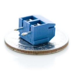
- 14 AWG screw terminals for relay connections.
- 10 AWG solder lugs for relay connections.
- Flyback diode included
- Zener recovery diode included (decreases turn-off time)
- Heavy 2 oz. copper on PCB
Documents:
- Schematic
- Eagle Files
- Hookup Guide
- Datasheet (JQX-15F/005-1Z1)
- Relay Tutorial
- GitHub
-
-
-
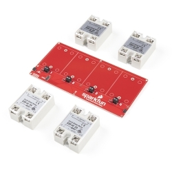
 SparkFun Qwiic Dual Solid State Relay
Special Price Current price: $59.95 Regular Price Original price: $149.95In stock
SparkFun Qwiic Dual Solid State Relay
Special Price Current price: $59.95 Regular Price Original price: $149.95In stock -
-
-
-
-
-
-
-


Features & Specs
- Voltage Rating: 220VAC/28VDC
- VCC requirements: 4-6V, 150mA capable
- SPDT pins exposed (Form C)
- 14 AWG screw terminals for relay connections.
- 10 AWG solder lugs for relay connections.
- Flyback diode included
- Zener recovery diode included (decreases turn-off time)
- Heavy 2 oz. copper on PCB
Documentation
- Schematic
- Eagle Files
- Hookup Guide
- Datasheet (JQX-15F/005-1Z1)
- Relay Tutorial
- GitHub
Customer Reviews

Stock and Customer Discounts
Available Discounts
- $9.74 | 10+ units
- $9.23 | 25+ units
- $8.71 | 100+ units