 Datasheet
Product Overview
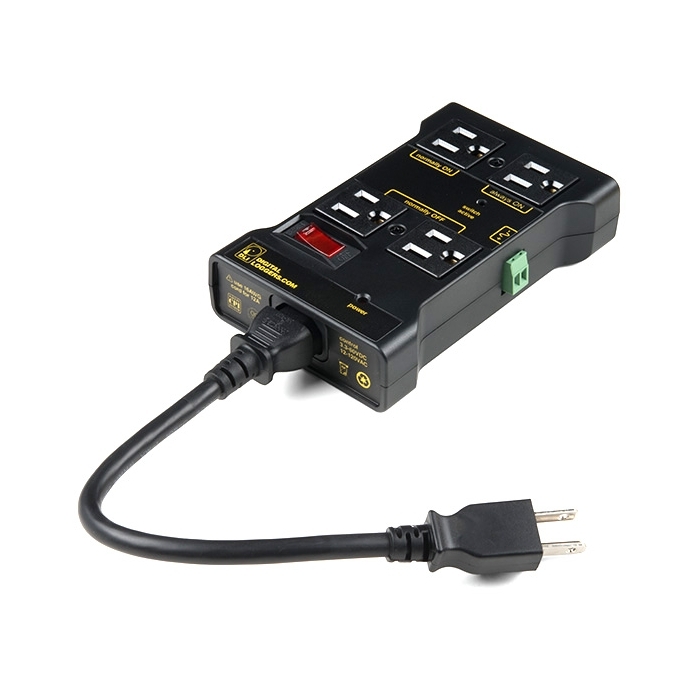
Do you want to control a standard wall outlet device with your microcontroller, but don’t want to mess with the high-voltage wiring? The IoT Power Relay is a controllable power relay equipped with four outputs that help you create an Internet of Things project with safe, reliable power control. With the IoT Power Relay you can easily control the power going to a device with an Arduino, Raspberry Pi or other single-board computer or microcontroller. It provides an alternative to the Power Switch Tail.
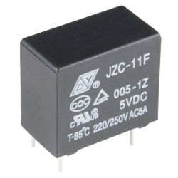
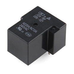
The IoT Power Relay is designed to allow you to safely control an outlet device that operates at 3--48VDC or 12--120VAC. Each IoT Power Relay features a single input (from the included C13 power cable) to four outputs: one normally on, one always on, and two normally off. The durable SPDT control relay is rated at 30/40A, for 400,000 operations.
Includes:
- 1x IoT Power Relay v2
- 1x C13 Power Cable - 24in


Features & Specs
- Universal control voltage 3-60VDC or 12-120VAC
- A single input signal switches four outlets: one normally on, one always on, two normally off.
- Optical isolation, relay hysteresis and de-bounce protection add safety.
- A large MOV clamps surges for clean 90-140VAC power.
- The durable SPDT control relay is rated at 30/40A, >400,000 operations at 12A or 2 million+ operations at 5A.
- A 12A thermal safety circuit breaker switch prevents overloads.
- Mounting tab with two screw holes
- Dimensions: 170mm x 95mm x 35mm (6.69in x 3.74in x 1.37in)
Customer Reviews

Stock and Customer Discounts
Available Discounts
- $35.63 | 25+ units
- $33.75 | 100+ units