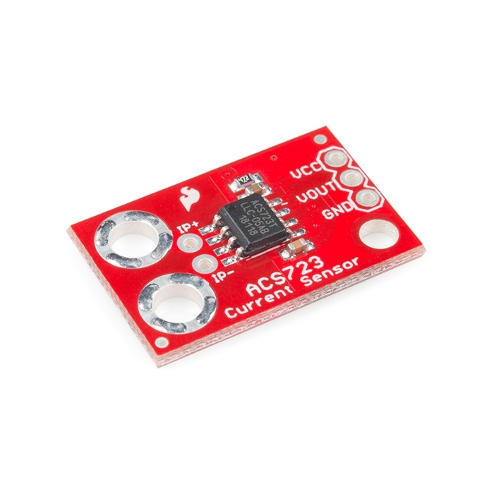
SparkFun Hall-Effect Current Sensor Breakout - ACS712

This is a breakout board for the fully integrated Hall Effect based linear ACS712 current sensor. The sensor gives precise current measurement for both AC and DC signals. Thick copper conductor and signal traces allows for survival of the device up to 5 times overcurrent conditions.

The ACS712 outputs an analog voltage output signal that varies linearly with sensed current. The device requires 5VDC for VCC and a couple of filter capacitors. Please keep in mind that though the ACS712 is rated for 2.1kV isolation, the PCB it is on is not designed for that type of voltage. Please keep that in mind if you are using this breakout in high voltage applications.

  • x05B (5 Amp) version
  • Low noise analog signal path
  • Device bandwidth is set via the FILTER pin
  • 5us output rise time in response to input current
  • 80kHz bandwidth
  • 1.5% output error at 25 degrees C
  • 1.2mOhm internal conductor resistance
  • 5.0 VDC, single supply operation
  • 185 mV/A output sensitivity
  • Output voltage proportional to AC or DC currents
  • Factory-trimmed for accuracy
  • Extremely stable output offset voltage
  • Nearly zero magnetic hysteresis
  • Ratiometric output from supply voltage
  • [Schematic](http://cdn.sparkfun.com/datasheets/Sensors/Current/ACS712 Breakout v11.pdf)
  • [Eagle Files](http://cdn.sparkfun.com/datasheets/Sensors/Current/ACS712 Breakout v11.zip)
  • ACS712 Datasheet
  • Hookup Guide
  • GitHub

SparkFun Hall-Effect Current Sensor Breakout - ACS712 Product Help and Resources

Maximum Current?

Using this calculator [ http://www.eeweb.com/toolbox/external-pcb-trace-max-current ], the board's traces can probably handle about ~3.56 Amps max.


Core Skill: Soldering

This skill defines how difficult the soldering is on a particular product. It might be a couple simple solder joints, or require special reflow tools.

1 Soldering

Skill Level: Noob - Some basic soldering is required, but it is limited to a just a few pins, basic through-hole soldering, and couple (if any) polarized components. A basic soldering iron is all you should need.
See all skill levels


Core Skill: Electrical Prototyping

If it requires power, you need to know how much, what all the pins do, and how to hook it up. You may need to reference datasheets, schematics, and know the ins and outs of electronics.

3 Electrical Prototyping

Skill Level: Competent - You will be required to reference a datasheet or schematic to know how to use a component. Your knowledge of a datasheet will only require basic features like power requirements, pinouts, or communications type. Also, you may need a power supply that?s greater than 12V or more than 1A worth of current.
See all skill levels


Comments

Looking for answers to technical questions?

We welcome your comments and suggestions below. However, if you are looking for solutions to technical questions please see our Technical Assistance page.

  • This is a great product and I highly recommend it to anyone. It measures current from AC or DC without any loss in load voltage. However there is a minor inherit problem. Because the output is Ratio-metric, which means with no load the out is 1/2 of Vcc. It also means if Vcc changes the output will also change that could cause inaccurate readings.

    To fixed this simply add a very stable 5V voltage reference thats capable of 20ma. I use these everywhere in my solar panel monitoring project

  • water_arduino / about 7 years ago / 1

    Does sparkfun actually read these? Last post was myself 7 months ago and nothing has come of it.

    • M-Short / about 7 years ago * / 1

      A handful of people do try to read all the comments, but but if you need answers to technical questions Consider posting a new topic on the SparkFun forums in the SparkFun products category.

  • water_arduino / about 8 years ago / 1

    Is there an actual wiring diagram for this product? How do you connect the terminal wires from which you are trying to measure a current? Do you just thread the cables through the 2 holes, or do you connect them with "X" size screw? Or do you solder a copper wire to the sensor holes? Do you solder it to one of the 4 little solder points, or anywhere to the hole? The tutorials and examples are garbage compared to what I am used to with sparkfun.

  • Member #737418 / about 8 years ago / 1

    FYI For non-power circuits this is likely not enough sensitivity. On the scale: 185mV / 1A, this is equivalent to 38 A/D counts per amp for 10 bit (1024 count) resolution (Arduino). That is equivalent to 26mA per A/D count resolution, as the A/D works at 4.9 mV / count. Could you make a more sensitive version?

    • water_arduino / about 8 years ago / 1

      I agree. When trying to send over a wireless network, I have to reduce the resolution even more to send from 1023 count to 255. Bleh.

  • Member #14938 / about 13 years ago / 3

    If you're using this to monitor DC motor current, watch out for the motor magnets. When mounted a couple inches from our PM DC motor we got a huge (~0.5 amp) offset in the ACS712 output. So, back to the sense resistor for us. Aside from that the ACS712 seemed good.

    • c6burns / about 13 years ago / 1

      These chips are part of allegro's hall-effect sensor line ... so yes they are going to be sensitive to magnetic fields

  • UnlimitedBacon / about 14 years ago / 3

    Is there any chance we could get this board with the 20 or 30 amp IC?

  • Koyaanisqatsi / about 10 years ago / 2

    @SparkFun Some suggestions for next time you order more of these for stock. I love this chip, but the PCB design renders this BOB nearly impossible to use.

    1. Pull the ground plane fill away from the screw holes. If I tighten a nut down on these, it grounds out on the fill copper because it's too close to the holes. Don't even fill on that side of the chip; just leave the PCB bare.
    2. Use smaller holes. It's only measuring up to 5A - we don't need #6 screws for that. Holes that accommodate a 3.5mm screw terminal would be optimum because we could solder in wires or a screw terminal.
    3. Add a couple holes for a .1 in header, like you did on the low-current version of the board. Except make sure they line up so it can go into a breadboard.

    • I totally agree. If you're measuring AC line voltage currents, I wouldn't recommend using this PCB -- the layout is downright dangerous. Whoever designed this board has obviously never done any mains voltage designs before, as this violates every creepage/clearance rule I've ever seen.

  • TestEngineer / about 14 years ago / 2

    Is there any chance we could get 20 of "ACS712" in one board?

  • hve / about 14 years ago / 2

    I vote for the 20 amp version as well. I would buy a few of them right now.

  • Member #643118 / about 9 years ago / 1

    I am considering using this breakout board with the ASC725-20AB, which can handle upto 20A, instead of the ACS712, which handles 5A. The new chip that I would replace would be connected to a wall outlet (max 15A b/c of the circuit breaker).

    Do you think the "survival of the device up to 5 times overcurrent conditions" would let it be ok if I draw ~ 15A on this breakout replacing just the chip?

    • survival of the device up to 5 times over current condition

      As mentioned in the datasheet "This device can survive 5 times the rated current i.e. 100 A current". But looking at IC Package i.e. SOIC-8 100A current would not be safe.

      For much precautionary measures , bury the input sensing pin with extra solder metal. So even if the IC gets damaged the pad of the PCB would remain safe.

  • Member #67540 / about 9 years ago * / 1

    BEWARE!! this breakout do not provide isolation to measure AC mains. The board layout do not have the required creepage (distances in the pcb surface) to measure voltages far from the microcontroller ground. A gap of 2mm under the IC and no ground plane in the bottom layer is needed to take advantage of the isolation offered by the IC manufacturer. " 2.1 kVRMS isolation voltage from pins 1-4 to pins 5-8" .

  • Member #635277 / about 9 years ago / 1

    Hi, I want to measure 5A output of a 220V 150/5A current transformer via this module. How do I do this?

  • Member #618705 / about 9 years ago / 1

    I need to monitor the amperage of a 460v 3phs pump. The load will be 2-3 amps, and I want to use one sensor on each of the legs. Will this sensor handle that voltage?

  • Member #564740 / about 10 years ago / 1

    In case this saves someone some time (since I just worked this out the hard way)... you can't use a current sensor with a stepper motor. Stepper motors run at full current all the time (so they can lock their position) so you can't detect (for example) an increase in current draw with an increase in load for current-control of the motor.

    • bdwyer / about 9 years ago * / 1

      I'm not so sure this is true. Stepper motors may have a constant current when it is holding a position (because the load is purely resistive during that time). When a there is some dynamic loading on the motor , there will be some transient change in current draw that should be seen in the phase windings. Not to mention, when the motor is actively being stepped, there will be transient currents during the active switching of the phase coils.

      A way to monitor the DC current used by a stepper motor, would be to measure before the switches (ie. monitor the current supply to the h-bridge V+ supply, assuming an h-bridge is used).

  • YusifNurizade / about 10 years ago / 1

    What formula is everyone using to convert Vout to current?

    Going by the graph I found in the datasheet I used the following:

    Current = [Vout - (Vcc/2)] * 5

    At 0.5A, I get more or less accurate readings but wild swings at 0.01. People below me in the commends have said they go 6mA accuracy and I'm wondering if I'm calculating wrong.

    Yusif Nurizade

  • Member #420074 / about 10 years ago / 1

    When I measure AC current Vout is AC voltage or DC Voltage? Thanks

    • RobLewis / about 9 years ago / 1

      The output is an analog waveform that tracks the sensed current (with a DC offset of +2.5V assuming you're using a 5V supply).

  • Member #478395 / about 10 years ago / 1

    What type of capacitors are those on the wiring example? Where can I find them?

  • Tresky / about 10 years ago / 1

    Is it possible to measure slightly more current than 5A with this? Say 7A or 8A?

  • Member #228791 / about 10 years ago / 1

    Can i measure 220V AC current with this one or any acs7xx sensors?(acs714)

    • RobLewis / about 9 years ago / 1

      It senses current, not voltage. So the supply voltage is irrelevant (except for possible isolation concerns).

  • the 1nf cap should be included.

  • JNM / about 11 years ago / 1

    If we are measuring AC current, does it matter which terminal we connect the hot and neutral to?

    • CF / about 10 years ago * / 1

      Nope. Either way will work. But put this in line (series) with your load.

  • Member #204950 / about 11 years ago / 1

    I have a line that sometimes carries 230V AC and other times ~400DC when it is rectified. I could not identify from the datasheet if AC and DC have different properties for this sensor, if voltage is much of an issue or if it is ONLY the current it senses...

    I will probably swap out the op-amp for a peak detector amplifier, I just need a Current/No Current detector that does not need re-calibrating with every current change . Can anyone advise me!!

  • Old Washed Up Engineer / about 11 years ago * / 1

    When measuring AC current, does it simply give a sine wave output voltage centered on Vcc/2? I didn't see anything specific in the datasheet about AC input/output, just that the output is above Vcc/2 for positive current and below Vcc/2 for negative current. So that's why I'm thinking that it just gives me the corresponding sine wave output (again, centered on Vcc/2). If so, has anyone used it with a microcontroller to measure AC current? And if so, how did you rectify the output into a suitable DC voltage for the ADC? I'm guessing the simplest way (which isn't so simple) is to run the output through an op-amp to stiffen its output impedance (and besides that, I need to amplify the output anyway because I'm measuring fairly low AC current, less than 250mA) with Vcc/2 as one input thereby centering the op-amp's output signal at ground (the datasheet shows an example of that; also, without split power supply rails, an AC signal into an op-amp would just give me every other "hump" of a half wave output, like one side of a center-tap xformer), possibly cap it to reduce the ripple, and then run that final output into the ADC. The last thing I want to do is bring in split power supply rails just for getting a better rectified AC output. What a mess...

    Has anyone does this? I feel the coming pain of lots of testing and screwing around to get this right, so I'm hoping someone's already done this who's willing to help a brother out :)

    Thanks in advance for any ideas at all! :D

  • Member #235716 / about 12 years ago * / 1

    alright, the example code in the Wiring Example is meaningless. I've tested my code with both ACS712-05B and ACS712-20A versions. Accuracy is within =- 3mA

    code: https://forum.sparkfun.com/viewtopic.php?f=6&t=33605&e=0

  • hazeo / about 12 years ago / 1

    I just tried using the ACS712 board but for some reason I only get 0.60v of response from the Vout even if i don't put any current source, which should give me 2.56v if the Vcc is 5v. Could it be that it got burnt when i was solding it? Or is there another posibility?

  • waspinator / about 12 years ago / 1

    what kind of header can you use for the big holes?

  • dvereber / about 12 years ago / 1

    Just a quick warning to not use this to sense your main Utility Line. Most of them in the US have a 200A breaker, which means that you could see as much as 200A in the line, which from the description above sounds like it would burn out the sensor.

    That said, most house circuits have 20A breakers, which shouldn't burn out this part, but it might not give you the data you want.

    • MikeGrusin / about 12 years ago / 1

      For sensing current through the mains, you'll probably be much better off (and safer) using a clamp-type current sensor such as the SEN-11005 in the related products below.

  • Progwhiz / about 12 years ago / 1

    Hi All,

    Is it possible to use this sensor to measure the input voltage being supplied to the controller to which this sensor is attached? Or is this only used to measure voltage/current on everythign but the power source to allow the sensor to operate?

    Thanks

  • justabill / about 13 years ago / 1

    Noob question here: What terminals should I add to the current pads to connect 14AWG wire?

    • RobLewis / about 9 years ago / 1

      It measures whatever current you run through it. Voltage is irrelevant.

  • tzikis / about 13 years ago / 1

    i would suggest uploading a new photo of the red PCB

  • acetate / about 13 years ago / 1

    30A demo board
    There is also a 20A demo board.

  • johndavid400 / about 13 years ago / 1

    hows about getting a version of the ACS714 like Pololu?? A +/-30amp version is a bit more suitable for robotics. I have used them and they work very well, would probably fit on this board.

  • wam / about 14 years ago / 1

    Here's a link to the Allegro dev kit for 20A:
    http://www.allegromicro.com/en/Products/Part_Numbers/0712/ACS712_Demo_Board.pdf
    note that's 4oz copper on top/bot with via stitching... see page 7 of the above link
    ... most quick turn PCB's houses don't do that heavy a copper... and if they did it would be $$$
    Link to the store $20.00:
    http://prostores2.carrierzone.com/servlet/AllegroMicroSystems/Detail?no=386

    Not sure if its in stock tho...

    WAM
    http://home.comcast.net/~ajawamnet/wc/wamcover.htm

  • SomeGuy123 / about 14 years ago * / 1

    Don't you think this is a bit overpriced?

  • MackLuDa / about 14 years ago / 1

    Could we get the cross sectional area, conductor width, and #oz. copper for the current traces? I'd like to compare them to the IPC Temperature Charts to see if your breakout board (with the ACS712-5A already supplied) can handle the 30A version.
    Or, if it's already been proven to work superbly under that condition (tested at 30Amax), I could just take Sparkfun's word for it. Thanks!

  • Erl / about 14 years ago / 1

    Suggestions for the next revision:
    Mark the 'positive' current direction on the board mask, for the two big holes (with an arrow ideally, or + and -).
    Also, standard size holes for the current connectors would be nice, to make it easier to connect headers. Perhaps in addition to the big holes?

  • Erl / about 14 years ago / 1

    I'd like to solder some standard male headers to the current pads, in order to be able to plug the board into a breadboard for prototyping.
    Could anyone advise as to if that would work (filling the remaining space with solder), or give some tips?

    • N8B / about 14 years ago / 1

      It would work, it would just be clunky. Use the breadboard as a jig. Make sure you don't get a massive blob of solder onto your breadboard.

  • stevegough / about 14 years ago / 1

    Is there a description of how to calibrate these things online anywhere?

  • Attie / about 15 years ago / 1

    Anyone know if this is suitable for the mains? say 3A max @ 240v AC (UK). I had a quick skim through the datasheet, and didn't seem to find anything :/

    • mattkenny / about 14 years ago / 1

      I'm using the 20A version of this chip in a device to sense mains current @240V/50Hz (Australia). It handles it just fine.

    • Chiel / about 15 years ago / 1

      the ACS712 is rated to 5A and after searching around on the web for projects using this ic at 220v i would say its usable in europe. the datasheet mentions a Peak Basic isolation voltage of ~380 Volt which could be the maximum voltage the ic can handle. i hope this answers your question.

Customer Reviews

2.7 out of 5

Based on 3 ratings:

Currently viewing all customer reviews.

1 of 1 found this helpful:

Not Arduino

Haven't quite got to the point of using and testing the units yet (6). My project is a 1.5 KW Vdmos Linear amplifier. I'm using the 712's for closed loop bias control. The fit and finish of Sparkfun products is always spot on and I've never had one problem with their products. I hope to have this project online in the next month.

2 of 2 found this helpful:

Anyone get this to work? I could not.

Has anyone had success with this sensor? With and without a 120VAC load, I always get a constant 2.5VDC output. A 300W (2.5 A) AC load should produce a 463 mV output, and a 640W (5 A) load should produce 925 mV output. I measure no change in output with a voltmeter. I have it powered and grounded by a 5V Arduino with the capacitors as recommended by the datasheet and the wiring.org example. :-(

1 of 1 found this helpful:

Works, but difficult to use

This little device works well, but the biggest problem I have with it is that it is little. It REALLY REALLY REALLY needs mounting brackets or something like in this video

https://www.youtube.com/watch?v=UF5jrnXvTlM

I have tried using nuts and bolts to attach wires, soldering, and crimp things. Everything is a pain, extremely difficult to use, and extremely easy to short.

Also, I had to dig pretty deep to even get an explanation on how it worked and how to set it up aside from the super basic explanation on sparkfun.

Also, would be nice if one like I mentioned above came in 30-50A version.