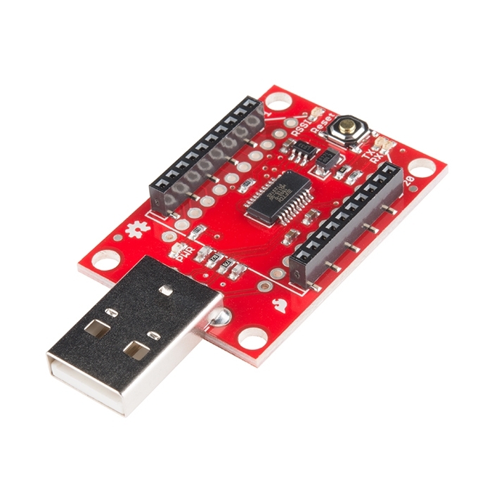
XBee Explorer Dongle

This is the XBee Explorer Dongle unit for the XBee line. With the XBee Explorer dongle you can now plug the unit directly into your USB port. No cables needed! This unit works with all XBee modules including the Series 1 and Series 2.5, standard and Pro version. The on-board voltage regulator is good up to 500mA.

You get the red board only. XBee modules sold below.

Not sure which XBee module or accessory is right for you? Check out our XBee Buying Guide!

Tags

Comments

Looking for answers to technical questions?

We welcome your comments and suggestions below. However, if you are looking for solutions to technical questions please see our Technical Assistance page.

  • Wayne / about 12 years ago / 2

    One constant frustration I have with Sparkfun's schematics for their breakout boards ia that they consistently omit part numbers for certain parts, such as power regulators. This makes it impossible to tell if the current available is sufficient. This board's schematic is a case in point, but there are dozens of other schematics lacking this critical information.

    • MikeGrusin / about 12 years ago / 4

      We're trying to be better about this, but you can ALWAYS ask. The voltage regulator is a MIC5219-3.3M5, datasheet here.

  • Member #590171 / about 10 years ago / 1

    Hello, Even though this product is retired, I somehow got my hands on it.Correct me if I am wrong,but I was wondering if it can be used to program an atMega328?If so ,how? Thanks in advance for the help :)

    • M-Short / about 10 years ago / 1

      Hi, this version of the board is retired, but we do have a current version available. As for programming this is basically an FTDI breakout board with an XBee footprint. It does do some voltage regulation as well, but its a USB to serial adapter. If your ATMega328 has the Arduino bootloader on it then you can program it over serial (connect power, ground, RX and TX) although you will need to do a manual reset since the board doesn't do auto reset. If your ATMega328 does not have the Arduino bootloader you will need to program over ISP with a dedicated AVR programmer.

  • Member #458594 / about 10 years ago / 1

    may i know when this product shall be produced back? I need to decide either to wait for Sparkfun, or buy from others (which is more expensive). My due date is near.

    • M-Short / about 10 years ago / 1

      The new version of both the [XBee Explorer Dongle] (https://www.sparkfun.com/products/11697) and the [XBee Explorer USB] (https://www.sparkfun.com/products/11812) are in stock. This part is basically retired (it should be officially retired on the site soon).

  • Member #146820 / about 10 years ago / 1

    WANT MORE XBEE DONGLES AHHWHWHH WMORE MORE MORE WHWEhhHHUnnnger why can these not be back ordered?

    • We've updated them. The new ones are available here.

      • Member #458594 / about 10 years ago / 1

        is it the same item? why the product code is different?

        • M-Short / about 10 years ago / 1

          They are functionally the same, there are a few changes like a newer version of the FTDI chip, a reset button, and some solder jumpers you can cut (useful for some higher end applications). When we make changes like this we give the product a new number. This helps you and us know which version you have.

  • Member #295919 / about 10 years ago / 1

    Using X-CTU software I can access/update the settings of the XBee module. However when using terminal emulator (the build-in of X-CTU or TeraTerm) doesn't work: can't access the XBee. What can be the reason of this problem? Thanks.

  • For enclosures, check John Biehler's design available through here => http://www.thingiverse.com/thing:24399.

  • Member #385080 / about 10 years ago / 1

    I have encountered a problem using the dongle with an XBee Pro S3B XCST. Digi.com tell me that the problem occurs because of a conflict between how different versions of their modems use pin 6. Since the dongle uses pin 6 as an indication of RSSI, the Xbee enters a diagnostic mode. This fully explained on their site (Knowledgebase item 3325). The solution is to cut the trace between the current limiting resistor and the led on the dongle board, the board will still function, simply less one led. I need to know which trace to cut please? Thanks michael

    • M-Short / about 10 years ago / 1

      Check out the new boards. We added a solder jumper on the RSSI line so you can cut the trace to disconnect RSSI.

    • Redneck EE / about 10 years ago / 1

      I tried that "fix". Still no luck with the S3B's, and now they're just collecting dust. XCTU wouldn't recognize the module to configure it, and tera term would return ERROR on most of the AT commands. I have since ordered a Digi interface board, but have not gotten back to them. I just keep using the S2B Pro's for now.

  • Member #240124 / about 10 years ago / 1

    I've been having a problem with the serial ports on my pc, the first port connected is automatically asigned to some windows communications and doesnt let me use it. Imrunning a windows 7 64 bit. Has anyone else had this problem? How do I solve this?

  • Member #485470 / about 10 years ago / 1

    I bought XBee Pro 900 XSC RPSMA, and XBee Explorer Dongle from sparkfun, it seems it not work together. it is the comments from digi tech support: "The Sparkfun boards are designed for the standard XBee modules and not the XSC product. The reason for that is that some of the pins on the XSC module do not have the same function as they do on the other modules. This causes the module to go into what we call Pitch mode which is what you are seeing."

    Please don't make same mistake as me. also some one can introduce me a USB dongle and TTL board for this XSC module ?

    • M-Short / about 10 years ago / 1

      Check out the new boards, they have a solder jumper on the back for RSSI. Cut the trace and you should be good to go.

    • Member #465339 / about 10 years ago / 1

      The XSC modules are compatible with this dongle with some minor hardware hacking. If you remove either the RSSI LED or its current limiting resistor (labeled as R4 on the schematic but it doesn't appear to be clearly labelled on the PCB) from the dongle, it should stop putting the radio module into Pitch mode. See this for more information: http://www.digi.com/support/kbase/kbaseresultdetl?id=3325

      • Member #385080 / about 10 years ago / 1

        I opted to cut the trace on the board and everything works fine now, it was very easy. I will also have to do it on the shield though and the trace there is harder to identify. The Eagle file shows a single line running to the LED, however the board appears to have two traces, one going to and one from. I am not sure which to cut.

        When you say remove the resistor or the LED, how is that done? Michael

        • Member #465339 / about 10 years ago / 1

          There's a tutorial here on how to remove surface mount components: https://www.sparkfun.com/tutorials/97

          As the tutorial mentions, there's always a risk of damaging other components or the circuit board when removing components, so go at your own risk. Another method would be to use a heat gun (one you might use for shrink wrap) to melt the solder around the component and then carefully remove with a pair of tweezers.

  • Member #484891 / about 11 years ago / 1

    Hey I have a few quick questions:

    1. Will this dongle work with the XBEE-Pro 900 RPSMA modules? As in these guys: https://www.sparkfun.com/products/9099

    2: How do I sent AT and API commands to the module? Using the terminal in XCTU?

    1. I can't reset several bricked XBEE-Pro 900 RPSMA modules I have. I tried writing the default firmware to the modules, but every time I test/query the module, I get the error where I have to hit the reset button. I tried shorting reset to ground, but that's not doing anything. Any help?

  • Member #358995 / about 11 years ago / 1

    Happy to find that the XBee Explorer Dongle works with my rooted Nexus 7 tablet running the Apps: USB OTG Helper and Usb Terminal. I used two XBEE S1 modules with default settings - one in the Explorer connected to the N7 by an OTG cable and the second connected to my PC running X-CTU (Terminal tab). Both terminals send and receive text from each other.

  • jucaferi / about 11 years ago / 1

    hi i bought the xbee explorer dongle and i connect an xbee s1 (not pro) on it. Then i also bought a xbee shield and an arduino uno and I connect them using stackable headers. I upload a simple program to the arduino that send signal to the dongle using serial.print but when i try to write from the dongle using the terminal on xctu I see that the dongle tx ligth blink and the xbee shield RSSI turns on for a while but the arduino dont receive signal on the serial.read(). Please I need a solution i am getting short of time. I need to be able to stable serial comunication wireless between my two serial 1 xbee what am i missing????

  • Member #412975 / about 11 years ago / 1

    Just thought I'd give everyone a heads up. This explorer cannot be used with the Xbee Pro 900 XSC S3B without modification. It took me a lot of research to figure out why. To use this with the S3B you have to desolder the resistor that goes to the RSSI led. Most Xbee modules use pin 6 as a signal strength indicator but on the S3B it is not. When pin 6 of this Xbee is pulled low on start up it enters a special mode that continuously counts up in hex. If you go to the terminal in X-CTU is will just be counting away. The resistor and led effectively pull down pin 6 enough to make it start in this mode every time. De-solder that resistor or led and it will work perfectly.

    • Member #452497 / about 11 years ago / 1

      Thanks from me, too! I bought this board because it has mounting holes, and the one I had been testing did not. Unfortunately, when I swapped this board in, my application went bonkers. A little snooping with minicom revealed the behavior you describe: ASCII hex values counting up with line terminators between them. I was still at a loss until I Googled "WRL-08687 xbee counting up" and found your post.

      Ripping out, er, desoldering that resistor corrected the immediate problem in that my application is now able to transmit and receive data as expected in the shop. Now for some real world long range testing...

      Thanks again!

    • Kibby / about 11 years ago / 1

      Thanks so much for posting this! This post prevented me from trying to do all that research myself! Glad I looked here first. :) Thanks again!

  • The Kontraptionist / about 11 years ago / 1

    Anybody design a 3D printable case for these yet? Also, Sparkfun, suggestion to change the LEDs to side-shining? My two cents!

  • Member #121516 / about 11 years ago / 1

    Does anyone know if there are drivers for the Raspberry Pi for this?

    • Member #437110 / about 11 years ago / 1

      When you connected it to the Raspberry pi, did you have it connected to a usb hub connected to the pi, or just connected it straight to the pi? Just wondering if the pi can provide enough current for it

    • conotech / about 11 years ago * / 1

      My recently purchased model B pi is running Raspbian. That image has the required FTDI drivers already built into the kernel.
      I am able to successfully communicate with the XBee. Port is /dev/ttyUSB0.

  • Member #375997 / about 12 years ago / 1

    Just bought the Xbee Explorer Dongle for use with XBee S1. X-CTU installed properly, but it does not recognize the dongle. X-CTU installation was verified by connecing an Arduino Uno to the USB port, which showed up in X-CTU. The XBee S1 module was verified separate from the dongle. What troubleshooting ideas are there for this case?

    • It sounds like your FTDI drivers aren't installing properly for the dongle to communicate with your computer. When you plug it in, try updating your drivers through your Device Manager. It should show up as a COM port after that. If that still doesn't work, shoot us an email at techsupport at sparkfun dot com and we will get you taken care of.

  • Member #363714 / about 12 years ago / 1

    OK I have the following question... When I connect the Xbee to this USB explorer dongle...

    Can I use this http://www.duracell.com/en-US/product/instant-usb-charger.jspx#BVRRWidgetID

    to power it? I will be using some xbee as routers.

    Thanks in Advanced

    • Progwhiz / about 11 years ago / 1

      The USB is powered by your PC and you dont need to power it independent of a PC. You cannot use the dongle unless it is communicating with a PC as the drivers are loaded onto a pc or controller before you can use the dongle.

  • Member #328249 / about 12 years ago / 1

    What is the best way for communicate with FDTI/ZigBee? FDTI Drivers or Serial Port? Can someone show me examples?

    Tks

    • Progwhiz / about 11 years ago / 1

      Both work well as one is a virtual serial and the other an actual serial port. The only thing that separates the two is dependent on what the ports capability are with respect to seed, buffer and error correction. These capabilities are what the FTDO or Serial driver currently supports. I have also found the bigger the buffer the better to ensure no overflow which is critical if you are receiving large amounts of data

  • Member #354678 / about 12 years ago / 1

    Hello.

    Can I use the Dongle with an RFBee? If not, which board should I use instead?

  • Member #338672 / about 12 years ago / 1

    XBee 2mW PCB Antenna - Series 2 (ZigBee Mesh)

  • stauffski / about 12 years ago / 1

    I purchased this item and two XBee Pro 900 XSC Wire modules. They both work fine communicating with each other, however, I cannot receive any data on the computer. I have no trouble transmitting, the loop back module receives and re-transmits, the USB module receives, but nothing happens on the computer end. Not in X-CTU software and not in custom C# COM software. RX and TX LED's light up on both units. Is this an issue on my end, or does this item not work with all X-Bee modules as some here have suggested? Any assistance in this matter would be greatly appreciated. Thank you.

  • Member #243046 / about 13 years ago / 1

    I m going to buy XBee Explorer, can any one tell me that either it act as virtual comport in window or communicate as specific device?

    • Toddintr / about 13 years ago * / 1

      @Member243046: When you plug it in, it shows up in Device Manager under Ports (COM & LPT) category as USB Serial Port (COM19) (well, it's COM19 on my system). You must first install the FTDI driver set. Because of the way the FTDI drivers are designed, in Device Manager under Universal Serial Bus controllers category, the entry USB Serial Converter also appears. You use a virtual serial COM port to communicate with this device.

  • Does anyone know if C# or C++ will work with this?

    • SomeGuy123 / about 13 years ago * / 2

      Most major languages will work. The module is made accessible as a serial device.

      • Ohh! (facepalm) So you don't program it, you can just talk to other Xbees with it! I am trying to get started with Xbees. Which would you recommend: getting one of these, or getting another Arduino?

        • SomeGuy123 / about 13 years ago * / 1

          Get one of these. Adding a full computer to your project may open many doors.

          • Well, what I meant was this: I could either get another Arduino, hook up an Xbee to that to communicate with my other Xbee, or I could use this adapter. In other words, why buy this when you can get an Arduino that does the same thing (with a little bit of extra code), and a lot more?

    • MikeGrusin / about 13 years ago / 1

      The driver creates a standard COM port, so yes, it will work with any language that can access COM ports.

  • Halfelf / about 13 years ago / 1

    Has anyone purchased one of these lately? Has the regulator been replaced with the 500mW regulator (MIC5219) that is now being used on the XBee Explorer USB (SKU WRL-08687)? And if so, can we get the product listing updated like the other one? I would think they both would have been updated at the same time, but it would be good to get confirmation.

  • Rude / about 13 years ago / 1

    soldering a jumper between the dio and din pins coupled with an old-school motherboard jumper is a great way to use this device to detect range capabilities in an xbee network.
    maybe this will help people like me when they are starting to experiment with these cool devices :)

  • BFMS01 BFMS01 / about 13 years ago / 1

    Will someone at Sparkfun come out and just answer the questions about these boards and the Pro models? I have 2 900 MHz modules, are these going to work or not. The regulated boards sure didn't.

  • ovidiup / about 13 years ago / 1

    For people asking how to reset a bricked XBee, follow the instructions here:
    http://www.instructables.com/id/Changing-Xbee-Baud-Rates/step5/Un-bricking-a-frozen-Xbee/
    Since the XBee Explorer doesn't have a reset button, take a piece of wire and short the RST pin on the back of the board to GND. You must do this while the X-CTU program displays the message window indicating it cannot connect to the XBee.

    • jnautique / about 13 years ago / 1

      I tried to short reset to gnd with a wire but that didn't work for me. If you read through the link, it suggests soldering on a couple of wires and running them to breadboard to create a reset button. I did this and was unable to unbrick all three of my Xbees.

      • Progwhiz / about 13 years ago / 1

        Try writing the configuration to the firmware using baud 9600 and using one of the preset firmware from the list, do not attempt to read the firmware before. For e.g. if you have a XBEE Pro series 2 use the XBP24 firmware option. I thought I had a few messed up XBEE's it seems some XBEE's dont come with a firmware preset. Only sure thing preset is the Baud at 9600
        Try it and see

  • Vert / about 13 years ago / 1

    A possible replacement for the regulator is MIC5319 from micrel. I haven't tried it yet but it claims a 500ma with a 200mv dropout. Same pinout and configuration as the one that is used on the board.

  • vanick / about 13 years ago / 1

    Does this work with the 60mW XBee PRO Series 1 module? The comments say it got some problems with the PROs...

  • comsian / about 13 years ago / 1

    can anyone tell me to establish a p2p connection between "xbee 1mW chip antenna" modules how many explorers i have to buy? If I buy only one explorer and configure one xbee and then the other and then place those in my circuit will it work? waiting for reply plz help...... thanks in advance

  • vameza / about 13 years ago / 1

    Hello. Reading the coments and discussion related, finally, the dongle can be used with pro versions of XBee???
    Another beginner question: put the dongle on the computer and just use x-CTU software to configure xBee??
    If so, all right!!
    See you all.

  • fle33.com / about 14 years ago / 1

    I am waiting for one of these to arrive with an arduino and a pair of 2.5 series chip xbees.
    I am trying to understand how it will appear in my PC. Does it show up as a com port that I treat as a serial I/O?
    Or is it a modem? I want to use Pure Data to play with it and am just trying to wrap my modest brain around it.
    The transition to software development has been slow for me.

  • crx / about 14 years ago / 1

    Does this enable DTR and RTS flow control? I am having trouble reflashing an XBee and I get the feeling that DTR and RTS are required.

  • Great little dongle works great, the only things I think could make this better is if there was a reset button on it, and if the indicators would be on both sides of the board or if they could be seenfrom both sides of the board.

    • comsian / about 13 years ago / 1

      can you please tell me how it works without a reset button.when i try to write my configuration the xbee it says press and release the reset button t ocomplete.....don't know what to do.....
      thanks in advance

      • faludi / about 13 years ago / 1

        You can also power-cycle the XBee to reset it, by gently lifting it out of the socket and replacing it.

  • hads / about 14 years ago / 1

    Does this version use the MIC5205? Back last year I suggested using the MIC5219 (which is the same format but 500mA) for the FunnelIO.
    Versions of the new FIO and all the XBee kit would be great with a regulator like that which supports the Pro power draw.

  • Rick8 / about 14 years ago / 1

    I've purchased several variants of the xbee explorer and just learned they will not work with all the PRO modules I've purchased. I know you are all about fun, but I'd appreciate a bit of QA on your offerings.
    Let me know when you have a version that supports the 500mA that the pro xbee variants use.
    remember spark-qa.com isn't registered yet...

  • Wiremetrics / about 14 years ago / 1

    I was under the impression the XBee Explorer's regulator only provides 150mA. It looks like this dongle uses the same regulator. My understanding is some of the Pro modules require 500mA. Has anyone been successful with these--maybe it uses 500mA in such short bursts that there is no problem?

    • Pearce / about 14 years ago / 3

      We're currently sourcing a better regulator.

      • Member #126811 / about 13 years ago / 1

        In http://www.sparkfun.com/products/8687 say that
        "Note: As of August 2010, all new boards now include a MIC5219 voltage regulator which is good for 500mA."
        AND HOW ABOUT THIS PRODUCT?

      • karma / about 14 years ago / 1

        1) What regulator part it has?
        2)I have already bought a dongle.
        How can I tell which regulator it has?

      • pjwerneck / about 14 years ago / 1

        The description is certainly misleading, since I bought this planning to use it with the XBee Pro 50mW and it's not practical. It simply can't supply current when transmitting and if I try to send more than a few bytes at a time the module resets.

    • bidontr / about 13 years ago / 1

      i saw a few holes under this card i wonder what would it be if i would set up an external power regulator unit and connect Vout pin of regulator unit to this dongles 3.3V hole?

Customer Reviews

No reviews yet.