PowerSwitch Tail

Replacement:COM-10747. We now carry the PowerSwitch Tail II! The new and improved design accepts a wider range of control voltages and can control loads up to 15A. This page is for reference only.

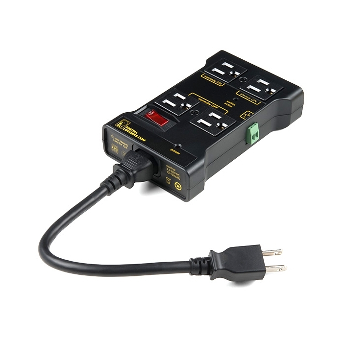
Want to control a standard wall outlet device with your micro controller, but don't want to mess with the high voltage wiring? This might just be the right device for you!

The PowerSwitch Tail is designed to allow you to safely control an outlet device without exposing any 120VAC voltages. You can plug in any standard 120VAC 3-prong outlet to be controlled by most any microcontroller. This will work great with Arduino!

Note: We are waiting on more stock for this item. We have been informed by the manufacturer that it will be several months before stock arrives. We estimate we will have stock later in the year.

  • Connect to Arduino, PIC, Stamp, or other MCU with driver transistor or ULN2803
  • LED indicator shows status of control signal
  • Connect output receptacle to a single powered device or to a power strip to control multiple loads.
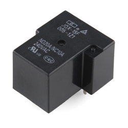
  • Switches up to 10A (resistive loads) with a 5VDC, 40mA control signal.

Comments

Looking for answers to technical questions?

We welcome your comments and suggestions below. However, if you are looking for solutions to technical questions please see our Technical Assistance page.

  • nibbler / about 14 years ago / 2

    Any chance of a 230v version of this, preferably also with IEC leads on both sides?

  • davr / about 14 years ago / 2

    It's not really that big of a deal, obviously this is not for battery powered operation, since you're plugged into the wall anyway. When you've got 120V and (up-to) 10A, 5V at 0.04A doesn't seem like that much.
    The driver circuit itself is pretty simple, a single resistor and a single transistor.

  • pzich / about 13 years ago / 1

    Ah, this is kind of exactly what I was looking for.

  • Member #114001 / about 13 years ago / 1

    Any idea when this will be back in stock? I need a few of these.

  • pp.kettu / about 13 years ago / 1

    It seems little silly that there isn't any (low-voltage) power source for the control logic, built in this thing. So if someone builds a device with this, he/she needs to plug in two separate power cords.
    But, it doesn't concern me anyway, unless you're planning a Euro version.

  • scurrier / about 13 years ago / 1

    Any idea why this will not switch off when I remove the 5V (even ground the positive side) when controlling a 150 watt compact fluorescent light?

  • qrry / about 13 years ago / 1

    Is there room inside the case for me to add a momentary switch in parallel to the relay?
    What are the physical dimensions?
    I would like to create a timer which powers various phone chargers for x hours. The button would be to begin the timer (powered by the output of the tail). The timer would then hold the relay closed for a period of time before committing suicide. This mechanism would live under a false bottom in a box.

  • nickbauman / about 13 years ago / 1

    The datasheet clearly states that the resistor to the base should be between 10-22k oHms but a 10k resistor isn't enough to trip the relay. When I use a 1k ohm resistor, it works well. I've tried it with an Uno and a Boarduino from Adafruit. Both exhibit this behavior. What am I doing wrong?

  • K1llaB1rd / about 14 years ago / 1

    BT: I know it's not that big of a deal, but you still can't drive it directly from most logic outputs. An SSR would also provide optoisolation...
    BTW, the schematic says that the Tail will still work with the J1 polarity reversed. True, but I don't think the TVS1 snubber will protect the drive circuitry in that case.

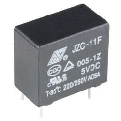
    1) Plain old electromagnetic relays (such as the one the Tail uses) provide isolation just as well as their solid state brethen (it's magnetic, not optical, but still works just fine)
    2) TVS1 appears to be a bidirectional TVSS according to the schematic. About the only issue I see with J1's polarity reversed is that the LED no longer works.

  • Ben121 / about 14 years ago / 1

    You could just use two outputs of most micro controllers.
    since most mcontrollers can sink 25ma on a pin (with some max per chip as well) you could probably drive this with any two pins no?)

    • Ivan747 / about 14 years ago / 2

      Thats REALLY dangerous. What if you forget to turn high one of the pins? Also is very dangerous to operate near the absolute maximum ratings. And dont forget that most of the inductive loads sink some extra current or produce current when switching betwen states. Better get a transistor or a ULN2803 wich has 8 transistors in one DIP package.

    • MoriFi / about 13 years ago / 1

      hmmm n-chan mosfet anyone

  • PaulC / about 14 years ago / 1

    jrisom: _
    Plus an SSR would not be ideal. It would only conduct in one direction which is bad for ac motors..._
    The description stated that this was only for resistive loads; if that's true an AC motor couldn't be used anyways.

    • jrisom / about 14 years ago / 1

      It gives the amperage limit for resistive loads. Inductive and capacitive loads have a different power factor which changes the amperage limit, so maybe 8 amps for an inductive load like a motor. The instructions state "Current capacity should be derated for inductive and capacitive loads." It's why there's a difference between watts and volt-amps.

  • BT / about 14 years ago / 1

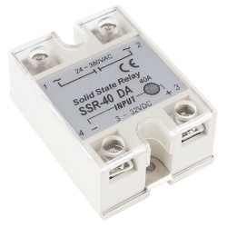
    I know it's not that big of a deal, but you still can't drive it directly from most logic outputs. An SSR would also provide optoisolation...
    BTW, the schematic says that the Tail will still work with the J1 polarity reversed. True, but I don't think the TVS1 snubber will protect the drive circuitry in that case.

    • jrisom / about 14 years ago / 1

      It'll still provide galvanic isolation. Sure you might lose a few thousand volts of protection compared to some optical isolators, but odds are you have a surge protector anyway which should keep it down to below your isolation limit. I would still throw in a 1n4148 snubber on the control circuit though.
      Plus an SSR would not be ideal. It would only conduct in one direction which is bad for ac motors, uses half the power for heaters, and probably double your peak current for an SMPS if it'll work at all. You'd want a triac which would still involve a voltage drop where the mechanical relay would have milliohm resistance which can be ignored.

      • thavinator / about 14 years ago / 1

        I believe you're thinking of an S C R. SSRs typically use back-to-back SCRs to provide bipolar operation. Otherwise it wouldn't be terribly useful in most cases for the reasons you mention.

  • BT / about 14 years ago / 1

    Unfortunate that the drive is so high, both in voltage and current. A 'Tail' using an SSR might be a better choice for uC power control...

Customer Reviews

No reviews yet.