- Home
- Product Categories
- Arduino Shields
- SparkFun Spectrum Shield

SparkFun Spectrum Shield
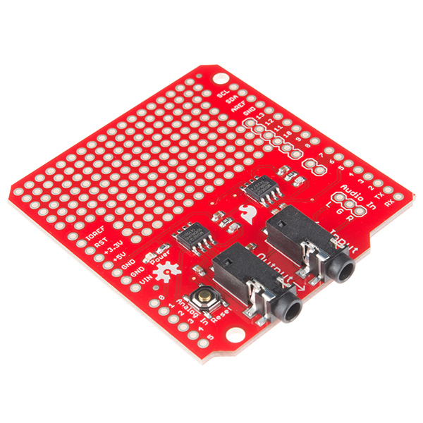
The Spectrum Shield enables your Arduino with the capability of splitting a stereo audio input into 7-bands per channel. You can then read the amplitude of each channel using the ADC on your Arduino allowing you to control everything from LEDs to motors, pumps to relays, or even fire, all with sound. With this shield you will be able to have almost any project be able to react to music or sound!
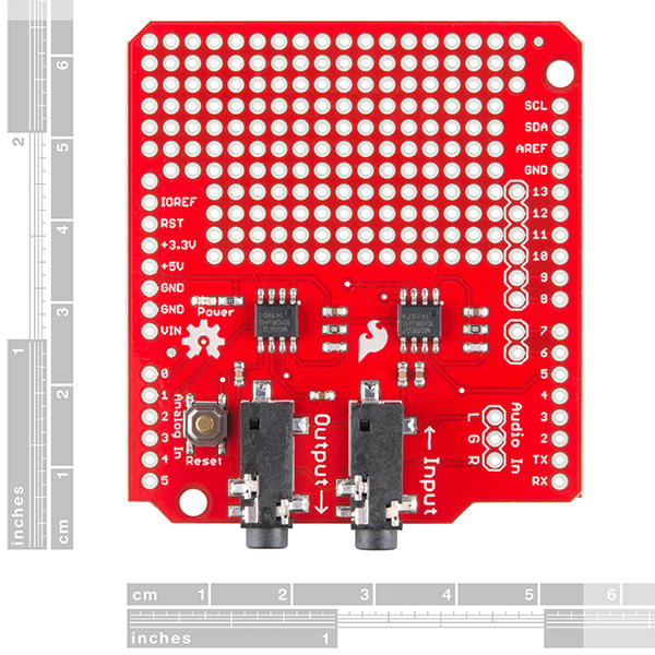
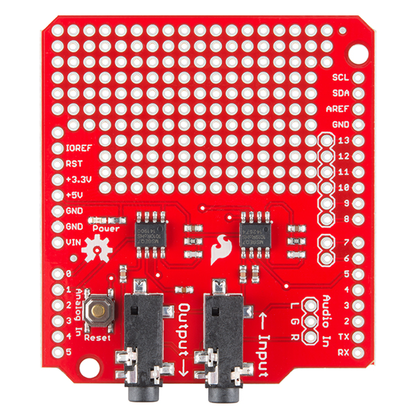
The Spectrum Shield features the MSGEQ7 graphic equalizer display filter. Two of these ICs allow you to split a stereo audio input into 7-bands (per channel) and read the amplitude of each using the ADC on your Arduino. The shield is populated with two 1/8" stereo jacks (like you would find on a pair of headphones). One serves as a stereo input and the other is a pass-through output which allows you to connect the Spectrum Shield in-line between your audio source and your stereo system without interruption. This revision of the Spectrum Shield has been updated to the Arduino R3 layout but still requires you to solder on your own headers (check the Recommended Products section below). This shield can be used to create sound visualizers, detect patterns in music or add sound activation to your microcontroller projects.
Note: This product is a collaboration with Ben Moyes of Bliptronics. A portion of each sales goes back to them for product support and continued development.
- Schematic
- Eagle Files
- Hookup Guide
- Datasheet (MSGEQ7)
- GitHub (Example Code & Design Files)
SparkFun Spectrum Shield Product Help and Resources
Interactive Hanging LED Array
April 10, 2014
Learn how we converted 72 lightbulbs into an interactive LED array for our conference room.
Hackers in Residence - Sound and Motion Reactivity for Wearables
October 3, 2014
How to consciously wear light-up and and sound reactive clothing.
Spectrum Shield Hookup Guide (v2)
May 4, 2020
Want your project to react to music? Then the SparkFun Spectrum Shield is the product for you! Get going in no time with this Hookup Guide.
**Audiophiles take note**
There is a lot of coupling with the I/O and the audio input. If you turn on the LEDs in the example code for a certain length, you will hear this awful buzzing noise. It's worse when you leave the LEDs partially or fully on. One suggestion might be to use a wireless audio Bluetooth and send the audio signal remotely so that it is not affecting the output. Audiophiles will cringe at the buzzing... Maybe some decoupling capacitors might help with the audio signal if you are splitting or putting your signal through the shield..
Core Skill: Soldering
This skill defines how difficult the soldering is on a particular product. It might be a couple simple solder joints, or require special reflow tools.
Skill Level: Noob - Some basic soldering is required, but it is limited to a just a few pins, basic through-hole soldering, and couple (if any) polarized components. A basic soldering iron is all you should need.
See all skill levels
Core Skill: Programming
If a board needs code or communicates somehow, you're going to need to know how to program or interface with it. The programming skill is all about communication and code.
Skill Level: Rookie - You will need a better fundamental understand of what code is, and how it works. You will be using beginner-level software and development tools like Arduino. You will be dealing directly with code, but numerous examples and libraries are available. Sensors or shields will communicate with serial or TTL.
See all skill levels
Core Skill: Electrical Prototyping
If it requires power, you need to know how much, what all the pins do, and how to hook it up. You may need to reference datasheets, schematics, and know the ins and outs of electronics.
Skill Level: Rookie - You may be required to know a bit more about the component, such as orientation, or how to hook it up, in addition to power requirements. You will need to understand polarized components.
See all skill levels
Comments
Looking for answers to technical questions?
We welcome your comments and suggestions below. However, if you are looking for solutions to technical questions please see our Technical Assistance page.
Customer Reviews
4 out of 5
Based on 15 ratings:
1 of 1 found this helpful:
Easy and Efficient
After soldering a few of the Sparkfun Spectrum Shield's connections and connecting them to the Arduino, the source code was easy to write. Adding the SparkFun Electret Microphone Breakout to the Spectrum Shield allowed a voice analysis instead of an audio cable input analysis. The Spectrum Shield paired with the Arduino and microphone lit up LEDs that corresponded to the frequency calculated by the Spectrum Shield. Easy to put together and very efficient!
2 of 2 found this helpful:
Reponds to Audio Characteristics of Phat Beats! Also: A Suggestion for Preventing Noise Issues in Some Applications
An excellent and relatively easy way to enhance a project with a sound visualizer!
One item of note: In my application, my stereo did not have an unused audio output that I could dedicate to the Spectrum Shield. For want of a better option, I connected the Shield in parallel with the speaker channels. Powering the Arduino/Shield from the same power source used by the stereo created a noise in the audio (high-pitched whine from the speakers) due to how ground is distributed in this configuration. **I should emphasize that this IS NOT a problem with the Spectrum Shield, just a problem with the only practical way I could install it in my specific application. However, there are only so many ways the casual tinkerer will connect this type of device. I imagine that others might encounter a similar situation.
My solution (admittedly not a very elegant one) was to isolate the Spectrum Shield audio input behind a 1:1 transformer (the off-the-shelf part is called a Ground Loop Isolator, ~$10 from several bigbox stores), this removed all noise and had the added bonus of preventing the audio input from floating; creating a clean, silent, signal for the Spectrum Shield to analyze when audio source was muted. Audiophiles will be quick to point out that Ground Loop Isolators often dampen or block the lowest frequencies. So If you are using the Spectrum Shield to create precision instrument, this solution may not be for you. For what its worth, I didn't notice a difference in performance with the Spectrum Shield behind an isolator with my sound visualizer.
TL;DR: If your project requires that your Arduino share power and ground with your audio source, adding a Ground Loop Isolator between your audio source and the Shield's audio input may address noise issues in certain situations.
1 of 1 found this helpful:
Does exactly what it supposed to do.
I have a project in mind and the Spectrum Shield seemed to fit the bill. I am a newbie when it comes to an Arduino and C, but have been very successful with the Basic Stamp since 2002. I ordered everything needed for the initial LED project from Sparkfun. Once built you need 7 different tones in different bands. You can generate them here: http://onlinetonegenerator.com/ or I’ve got them in a zip file you can download here: https://snsemp.com/shield/ . Needless to say I wasn’t pleased when the supplied code didn’t work. Then I found this: https://forum.arduino.cc/index.php?topic=507766.0 . The author was able to print out a table for the values of the tones when played, the Spectrum Shield generated. You can download the comparison value charts I made, along with the final code here: https://snsemp.com/shield/ . Like I said I don’t know much about C but I can “back engineer” existing code. You will need to download a library ( https://github.com/NicoHood/MSGEQ7 ). I stripped out what wasn’t needed and added a few lines to bring the pins HIGH or LOW, and now when the tones are played it works like a charm. This is nothing fancy; it just turns on the corresponding LED when the tone is played. This is the first time I’ve ever programed an Arduino, just glad the Spectrum Shield’s circuitry was solid. All coding credit goes to the above folks. Now to replace the LEDs with relays.
3 of 3 found this helpful:
Works Extremely Well - Noise Not an Issue
This board is really good at what it does. The 2 MSGEQ7s really work well. It is worth noting that the hookup guide is incorrect. The reset for the MSGEQ7s is tied to pin 5, and the strobe is tied to pin 4. I highly recommend keeping the input aux cable as short as possible to mitigate noise. When reading back data, all of the frequency bands settled to an Arduino analog value of ~60 with no signal (which is totally fine relative to the 1023 max value). Be careful to calibrate the imput volume level so you don't get clipping. I found that 100% volume on my computer clipped the middle values significantly. About 75% seemed to work great.
Thanks for the feedback - we updated the hookup guide to reflect that!
3 of 3 found this helpful:
Does its job well
Nice little board that does a specific thing (reading stereo audio levels over 7 different frequency ranges) very well. Easy to use with an Arduino, and the shield has enough room to mount a pro mini board right on it. The audio in and audio out is a nice feature (allowing stereo audio through).
2 of 4 found this helpful:
Noisy Junk - Worst $30 ever spent
I am very disappointed in this board. There is so much that needs to be done in software to eliminate the noise and then artificially inflate the input readings that this board is nearly useless for anything other than maybe giving four or five levels of actionable values. I've read in many other places that there are much better ways to hook up and utilize the MSGEQ7's. Do yourself a favor: since this board requires some soldering anyway, spend a couple bucks and get the IC's themselves and a couple other components and build something yourself. Skip this dud. I will be desoldering my Teensy from this board ASAP. I heartily wish I could return it.
Hi, Please drop us a line directly. We'll be happy to work with you on this. Thanks - https://www.sparkfun.com/returns
my spectrum analyser is not working correctly
all bands are almost equal (always) i have checked it with sound generator
Hello there! Sorry to hear you're having trouble. Send an email to us at techsupport@sparkfun.com and we will help you with this.
Noisy/doesn't work
I bought this for a Christmas light/music project. Using the Sparkfun supplied code in the hookup guide, it barely worked. Emailing with tech support, they didn't seem to understand what the code was even suppose to do. That surprised me, and left me with little confidence in Sparkfun products. Users have written code to help eliminate noise issues, and I'll try that code when I get some time. But read the comments and reviews before you buy this. It did not work for the example provided in the hookup guide.
Perfect for my giant spectrum display.
The project space makes integration in my project clean and tidy. Exactly what I needed.
Very good Support but after 2 hours one MSEQ7 broke
The workmanship of the shield is very good. Unfortunately, after 2 hours, one of the two MSEQ7s broke. Only one channel works like this. Very sad.
0 of 1 found this helpful:
Was bad now better
Revised Original post Another poor buy, I had bought this board last year before the took them off the site to fix a problem with the old board. When this model came back online I was very excited to be able to build with it again. The only problem is once I bought it and set up my circuit, it only worked properly for about an hour. After this it began to have a heavy noise interference and not work properly. Very disappointed.
After talking to the people at Sparkfun we realized it was just something small and I was able to edit the code to cut out the extra noise that was causing weird effects on my project. It works now but just not to the full potential but it is working so that is good. I would buy it again but I would be more hesitant about it.
Very decent part
Pretty easy to use. Takes less than 15 minutes to set everything up and run. Have not encountered any noise issue like some folks mentioned.
Works great!
This was exactly what I needed to add audio detection to my project. Sample code worked perfectly and sped up development. Thanks!
Quality board
Very quick and efficient at what it does. Sparkfun has always made quality products and continues to make more!
Great board for audio projects
This is a fantastic little board for quickly adding audio analysis to any music related project! I used this shield, along with an RFM69 wireless transceiver, to broadcast the readings to an LED cube I 3d printed. The linked hookup guide was easy to follow and quick to get started.
One small gripe did I had with this board was that analog pins 2-5, digital pins 2 and 3 (interrupts), and Tx/Rx are not broken out in the same fashion as digital pins 6-13. I used standard male headers to keep the footprint small, which meant I had to solder a jumper wire to any of those pins. If you plan to utilize any of those pins, I recommend using the stackable headers. Aside from that, this is a perfect little board.
Hey Gang, the shield I recently received had the Reset pin on D5, not D6.
I just noticed the same thing (reset on D5 and not D6). Is this change intentional? The posted schematic still has the reset on D6. On one hand this is concerning as it means that I have to change some code to make things work (and have to do some resodering). On the other hand this does mean that you can now use the spectrum shield with the Adafruit NeoPixel Shield (http://www.adafruit.com/products/1430) for lots of blinky fun as it uses D6 as the control line for the NeoPixels.
Final feedback is, let us customers know when a change is in the works and when that change has been made.
Sorry about the confusion! We accidentally had the old hardware files listed on the product page. The reset pin is now on D5, and the files will be updated asap to reflect that.
Hi, can I use this shield with an Arduino MEGA?
I'm working on a project to connect a metal detector to an Arduino and analyse the amplitude/frequency of the input sound for automated metal detection on a robot.
The data sheet wires the left and right channel from the audio into the msgeq7 with 2 22k resistors for each channel into the .01uF(10nF) capacitor then into the Audio In pin but I’ve seen other people (like this shield) hook it up with only the capacitor, either 10nF or 1nF. what is the difference between using the 22k resistors+capacitor vs the capacitor only? and also is there a benefit when it comes to output readings when using 1 msgeq7 for mono or using 2 msgeq7’s for stereo reading left and right independently? thank you to anyone who responds :)
This has been on backorder for sometime. Is it being replaced? Any thoughts on an update that auto filters noise? In canada my usual sources say they no longer sell this.
There are currently no plans to replace this, we are just waiting on a part which seems to be taking a while. I don't currently have an ETA, but keep checking back.
I want to use this to connect between speaker and amp instead of line in. Thanks to someone's code, I got a basic vu meter going on line in, then I put the contraption between speaker and amp. After adding a few hundred ohms of resistance, I had a amp monitor that worked well. I figure the impedance is so high this thing won't get hurt, but am I missing something? Seems too easy.
Would I be able to use this board hooked up to an external mic board that's sampling music instead of using the stereo Jacks?
I have this :Electret Microphone Amplifier - MAX9814 with Auto Gain Control https://www.adafruit.com/products/1713 Thank You
Another poor buy, I had bought this board last year before the took them off the site to fix a problem with the old board. When this model came back online I was very excited to be able to build with it again. The only problem is once I bought it and set up my circuit, it only worked properly for about an hour. After this it began to have a heavy noise interference and not work properly. Very disappointed.
For anyone looking for a place to start, I made a compact class for the shield (very bare bones, but it makes the application code look really nice). Copy the code below labelled "Header File" into a file called "Sparkfun_Spectrum_Shield.h" and the code labelled "CPP File" into a file called "Sparkfun_Spectrum_Shield.cpp" and put both of those into your Arduino project folder.
Header File:
CPP File:
Example Main .ino File:
This is really great - we'd love to add this to our repository if you'd like to do a pull request.
I wish I could return it. Reset pin on 5 instead of 6 so if you are trying to follow examples, good luck. Ridiculously noisy. Don't buy this thing. Not worth $10, much less $30.
This shield puts the FUN in SparkFun! (Sorry)
Wanted to share code for newbs like myself who found the examples didn't work quite like I was expecting. This code uses the same board / LED configuration as SF example, but produces more of a peak level meter.
A good tip from the linked github repository points out that the A0 and A1 pins are reading left and right channels. The code grabs all 7 frequencies from both channels, adds them up, and lights more LEDs the higher the number.
One code mod to try is lighting all LEDs just on the highest sum which will typically cause the lights to strobe to the beat. You may need to adjust thisSum ranges according to your card / audio source.
Is there any reason why you chose pin 4 & 6? I dont see any real logic for this decision. Just asking because I am coding an MSGEQ7 Lib with examples. And those examples should work with the shield as well. Was there any intention behind this?
I have a similar question about the reset pin (pin 6). Pin 6 is one of the PWM pins but this would seem to take it out of the running for use driving something that needs PWM.
Just thought I'd share this: On my shield, Pin 6 is not connected to anything at all! Reset goes to Pin 5, I repeat Pin 5!! It has taken me a year to realise this and explains why I haven't been able to make it run through less than the seven bands. I've checked the board thoroughly and I'm afraid, Sparkfun, it's not me that's mad. Just wondering how this passed your testing? So countless people out there are carefully timing the reset when there is nothing connected to it - how mad is that?
Is there any update on when this will be back in stock?
I've been working with this version of the spectrum shield for a few weeks now and I've noticed something. Both equalizers return values on each of the bands when there is no input ( < 100 ). This happens both when there is no audible signal coming over the input line and when there's nothing plugged in to the input line at all.
Is this an expected behavior?
Got mine a week ago but having problems audio out - the audio doesn't sound right when it pass through the shield. Tried different 4 male to male audio cables (cables them self work fine), different audio source and headphones/speaker. Also tried it with power on and off. seems like something wrong with the shield I got :(
We discovered an error in the PCB on these that is causing the issue you're describing. The ground on the input jack is not connected to the rest of the board. If you connect the pin on the jack closest to "UT" in the word "<-- Input" to either "Audio In, G" or the same pin on the output jack this will correct the problem. A revision is in the works to permanently fix this. If you have any questions, email us at techsupport@sparkfun.com.
Cool....so you definitely didn't even remotely try to test this device before you started selling it. I mean, I make mistakes like this on boards all of the time, but plugging it in and making sure it functions tends to bring those kind of issues to light.
When it's back in stock, will those boards be the updated version?
We test every single board, but unfortunately in this case, our test bed is not capable of catching this particular error. All the affected boards were pulled from stock once this issue came to light and that's why they are currently on backorder. If you have one of the affected boards, please email us at techsupport@sparkfun.com and we will take care of you. All new stock will have this problem corrected.
Nice to see that this product lives on (=gets updated). :-)
I still don't understand why you have two jacks for "passthrough" when a simple 3.5 mm stereo splitter is a rather cheap and flexible solution. It would possibly make sense if you had some sort of "jumper" so that you could separate them and one as input and the other as modified/filtered output based on your own MSGEQ7 code but as far as I can see there are just straight traces between the two jacks.
IMHO a compact MSEQ7 breakout board would probably be more convenient in several cases (compact speaker builds etc).
It would be very convenient to either have a small board with the necessary MCU pins in one end, audio "LGR" pins in the other end and two MSEQ7 chips with checked/"tuned" support components in the middle OR a similar compact board with a single 3.5 mm jack in the "audio" end and all 8 pins (VCC, GND, Reset, Strobe, AnalogOutL, AnalogOutR, AudioInL ,AudioInR) on the other end.
That way you could use it as a slightly longer but much smarter version of the 3.5 mm jack breakout board.
The extra stereo jack adds around $0.10 to the cost of the board, and it useful for those not having a splitter lying around. It is good that it was kept. There are compact breakout boards available (Google is your friend). I think this is the only Arduino shield though.
hello, I am working on a project using the spectrum shield to have leds react to music. The sprectrum shield has an input and an output, one for the speaker and one for the stereo input from phone. Question is I want to use a Bluetooth speaker so we can send the music wirelessly through phone, will it work like that? so the input jack wont have an input
When do you expect these back in stock?
Looking at the schematic, C1 and C3 are given as 1,000pF. When I look at the data sheet (http://www.mix-sig.com/images/datasheets/MSGEQ7.pdf) the values are given as 0.1uF (100,000pF). It seems like this deviation may mean some of the sharper volume peaks are missed? I could be wrong ...
I see you're using the SMD version of the MSGEQ7. Will you be selling them?
The SMD version is available on eBay. You might also have luck asking MSI (the manufacturer) for samples.
Has anything changed from the previous version besides the header layout?
General production upgrades to improve the quality to all users. Also, there's now a shiny new hookup guide ;)