Please see all COVID-19 updates here as some shipments may be delayed due to CDC safety and staffing guidelines. If you have an order or shipping question please refer to our Customer Support page. For technical questions please check out our Forums. Thank you for your continued support.
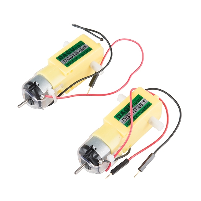
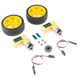
These are a pair of hobby gearmotors from DAGU. These gearmotors are the same ones recommended for use in the Shadow Chassis and offer a cheap and easy-to-use setup to get your wheels turning. Each Hobby Gearmotor also possess a 9mm long output on a straight axis.
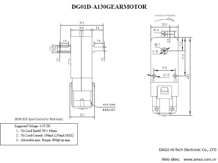
These gearmotors require a voltage of 4.5V with a no load current of 190mA while possessing a gearbox ratio of 48:1 and a wheel speed of 140 RPM unloaded.
Every motor order is sold in packs of two.
Note: The RPM listed in the datasheet below is listed as 90RPM. Based on our own testing we found the gearmotors can actually achieve a No Load Speed of about 140 RPM.
This skill concerns mechanical and robotics knowledge. You may need to know how mechanical parts interact, how motors work, or how to use motor drivers and controllers.
Skill Level: Rookie - You will be required to know some basics about motors, basic motor drivers and how simple robotic motion can be accomplished.
See all skill levels
If it requires power, you need to know how much, what all the pins do, and how to hook it up. You may need to reference datasheets, schematics, and know the ins and outs of electronics.
Skill Level: Rookie - You may be required to know a bit more about the component, such as orientation, or how to hook it up, in addition to power requirements. You will need to understand polarized components.
See all skill levels
We welcome your comments and suggestions below. However, if you are looking for solutions to technical questions please see our Technical Assistance page.
Based on 2 ratings:
1 of 1 found this helpful:
As is common with a lot of things made in China, these simple motors with their plastic gear trains won't last forever. Tried using them for a project, but after a several hundred hours of use, they will die out. In my case, the motors would either spin very slowly as if someone had their thumb on the scale or they'd work sporadically. Sometimes the lights on my red board would blink indicating that power was being directed to them, but they wouldn't spin at all.
They're suitable for projects that don't require anything too durable or strong, but if you want something that will last longer, look into getting Sparkfun motors with gear trains made out of metal.
I'd personally like to have more options for made in USA electronic parts instead of China or at the very least made in Japan, South Korea or Europe.
Putting your encoders on the extra shaft of these motors is definitely the way to go. With a simple 4 blade optical interrupt encoder I'm getting very accurate distances. I get 384 ticks per wheel rev.
This is a WAY better setup than putting encoders on the output shaft. Finally a cheap robot that drives straight!
Is there a CAD file available?
The black and red wires on the gearmotors shown in the picture above look like mirror images (red/black then black/red), however mine look the same - meaning the wires colors are the same on the left and right on each gearmotor. Mine are both black on the left/top and red on the right/bottom when I place them facing the same way as the picture shown on the website - is this wrong? Do I need new ones? I don't think I can flip one over - I think they came already soldered on... plus my car just drives in circles.... help!
The colors are nice, but not always that useful. For a DC motor if you apply power it will spin in a certain direction. If you apply that power in reverse it will spin in the opposite direction meaning there is no "correct" way to connect it. So it depends on how you mount it and your code. If you have it mounted the way you want and don't want to fiddle with code I would just swap how the wires are connected to your motor driver.
Forgive my lack of technical language, but these look like they have one shaft coming out of the top and two that stick out of the sides. The top one is a long and skinny metal shaft and the other two look like plastic. My question is, do they all three spin?
Yes they all spin. The skinny metal shaft is typically used to add a wheel encoder. The wheel encoder allows you to determine how far you wheel has turned. This metal shaft turns at the same rate as the motor and is not effected by the gears. For this motor for every turn of the wheel (the plastic shaft) the metal shaft will turn 48 times (since its 48:1 gear box).
The other two plastic shafts are to attach a wheel. I only use one of these shafts to attach one wheel. The other plastic shaft goes unused in my robot.
What's the backlash like on these motors? Would it be small enough for a balance bot?
How would i go about mounting this to anything?
These were definitely not designed for ease of use. There are two through holes where the motor mounts to the transmission. I think they are 3mm. There is also a small tab at the center front of the gearbox with a hole. You need to use bolts or sometimes I just use 3/32 pop rivets if I am not planning to remove them. I can speak from experience that the gearboxes are made from some sort of high molecular weight plastic (I'm guessing polypropylene or polyethylene) and no glue will stick to them---I've tried pretty much all the choices. VHB tape might work for temporary installation.
Hurrah! Tail shaft! Thank you for enabling encoders. What is the diameter of the tail shaft?
Can these go forwards and backwards?
Yes.
Do they come pre-wired to connect to the RedBot mainboard?
The photo's don't show the wires....
You need to solder on the wires
What wheels can be used with these?