- Home
- Product Categories
- DC/Gearmotor Driver
- SparkFun Serial Controlled Motor Driver

SparkFun Serial Controlled Motor Driver
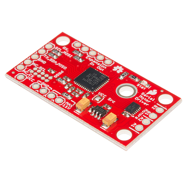
The SparkFun Serial Controlled Motor Driver (SCMD) is a DC motor driver that’s been designed to drive small DC motors with ease. The SCMD is designed to emulate a typical register-based device in operation. It can be commanded by UART, I2C or SPI communication, and it can drive a constant 1.2A load per motor (peak 1.5A) at 11V. Need more than two motors? Chain multiple SCMDs together and command them through the same serial interface. Need more current? Each board’s output can be bridged to allow double current.
This driver board was designed to be affordable, compact and have more features than previous versions of serial-controlled motor drivers. Its main advantage is the variability of drive levels, making fine control adjustments a possibility. The SCMD is a 3.3V logic device! If you need to interface to 5V, you'll need to use a logic level converter -- or modify the SCMDs from stock to operate at 5V and supply your own regulated 5V.
- 1.5A peak drive per channel, 1.2A steady state
- Operates from 3 to 11 volts with 12V absolute max
- 3.3V default VCC and logic
- Max VCC in of 5.5V
- 127 levels of DC drive strength.
- Controllable by I2C, SPI or TTL UART signals
- Direction inversion on a per motor basis
- Global Drive enable
- Expansion port utilizing I2C, allows 16 additional drivers
- Exposed TO-220 heat sink shape
- Several I2C addresses, default UART bauds available
- Bridgeable outputs
- Optional fail-safe and diagnostics available.
- Configurable expansion bus bit rate to 50, 100 or 400kHz.
- Configurable expansion bus update rate from 1ms to 255ms, or by command only
SparkFun Serial Controlled Motor Driver Product Help and Resources
Serial Controlled Motor Driver Hookup Guide
November 17, 2016
Hookup guide for the Serial Controlled Motor Driver
WiFi Controlled Robot
May 2, 2018
This tutorial will show you how to make a robot that streams a webcam to a custom website that can be remotely controlled.
Assembly Guide for SparkFun JetBot AI Kit V2.0
March 27, 2020
Assembly Guide for the SparkFun JetBot AI Kit v2.0. This tutorial includes photos & comments to assemble the two-layer chassis & additional components unique to the JetBot kit.
Wireless Joystick Hookup Guide
January 5, 2017
A hookup guide for the SparkFun Wireless Joystick Kit.
Core Skill: Soldering
This skill defines how difficult the soldering is on a particular product. It might be a couple simple solder joints, or require special reflow tools.
Skill Level: Noob - Some basic soldering is required, but it is limited to a just a few pins, basic through-hole soldering, and couple (if any) polarized components. A basic soldering iron is all you should need.
See all skill levels
Core Skill: Robotics
This skill concerns mechanical and robotics knowledge. You may need to know how mechanical parts interact, how motors work, or how to use motor drivers and controllers.
Skill Level: Rookie - You will be required to know some basics about motors, basic motor drivers and how simple robotic motion can be accomplished.
See all skill levels
Core Skill: Programming
If a board needs code or communicates somehow, you're going to need to know how to program or interface with it. The programming skill is all about communication and code.
Skill Level: Rookie - You will need a better fundamental understand of what code is, and how it works. You will be using beginner-level software and development tools like Arduino. You will be dealing directly with code, but numerous examples and libraries are available. Sensors or shields will communicate with serial or TTL.
See all skill levels
Core Skill: Electrical Prototyping
If it requires power, you need to know how much, what all the pins do, and how to hook it up. You may need to reference datasheets, schematics, and know the ins and outs of electronics.
Skill Level: Rookie - You may be required to know a bit more about the component, such as orientation, or how to hook it up, in addition to power requirements. You will need to understand polarized components.
See all skill levels
Comments
Looking for answers to technical questions?
We welcome your comments and suggestions below. However, if you are looking for solutions to technical questions please see our Technical Assistance page.
Customer Reviews
5 out of 5
Based on 1 ratings:
awesome
easy to connect and to code !
I am currently playing around (communicating with a raspberry pi over I2C) with two of those drivers (one master and one slave connected over the expansion port). I am able to control motorspeed, etc. just fine. However I was a bit surprised, when I realized that the failsave only centers the master motorspeed (when I loose connection between raspberry pi and master). The slave drives on. He only stops when he looses connection to the master. Is this wanted? What would be the best solution, if I wanted to disable all motors, when a failsave occured?
I'm going to have to play with this for a bit and get back to you. It involves doing a remote write to the slave's FSAFE_CTRL register, and possibly using FORCE_UPDATE to issue motor speed updates rather than relying on the periodic updates. I thought no one would try to do this! (but I left provisions anyhow)
It would help if I had the following info:
If you like, you can contact tech support via email and get a hold of me through them! Thanks for asking!
I found a simple solution that works (for me): I set the FSAFE_CTRL register that way, that if a failsave occurs, the master reboots. This way it resets the speed of all slaves, too.
Can someone verify errors in the data sheet? Specifically, the FSAFE_TIME (0x76) Function/Notes in the register map are wrong? Also, 0x15 says FSAFE_CTRL in the register map, but PAGE_SELECT in the description. Which is it?
Hello has anyone gotten this to successfully work with a Raspberry Pi 3 I have tried a thousand diffrent things but cannot get this to work.
Hi there, it sounds like you are looking for technical assistance. Please use the link in the banner above, to get started with posting a topic in our forums. Our technical support team will do their best to assist you.
That being said, this is probably outside their scope. However, we do have a Python pacakge for the SCMD. Unfortunately, there is no documentation on the package beyond the ReadtheDocs at the moment.
I am currently controlling the SCMD via SPI (< 1MHz). Is it normal for it to take ~30 seconds to enumerate? From the documentation it seems enumeration should end around ~1 sec. I have implemented my own driver based off the github driver, but my ready() function is blocking very consistently for about 30 seconds. Once it returns true, everything seems to work very well after that. Is there a way I can force it to not enumerate if I only have one master (no slaves) in my design?
Thanks!
Solved my problem...for those that might have run into a similar issue. I hadn't soldered the jumpers to enable the pullups on the expansion port. The controller must've detected there was an error on the i2c bus and initiated some other timeout delay...more than just a "did not receive an ID from a slave and increment the poll count". Probably timed out that whole process after 30 seconds.
Just out of curiosity, what is the copper finish on the bare PWB? It looks as flat as ENIG, but it isn't gold. How does that finish compare in a production environment (cost, solderability, resistance to tarnish/oxidation) to other finishes?
Can the PSoC 4245 in the board be programmed?
edit The answer is yes, I found the C firmware on github, how did you compile it and how did you program the board? Some pointers would be appreciated.
Hey, I wanted to put a few more thoughts in here. If you're the type that ends up with random psoc dev kits, many of them can be used to flash and for debugging. For instance, I use a CY8CKIT-042-BLE kit because I didn't have a miniprog3 handy.
To recompile from the github repository, use cypress PSoC creator 3.3 and set the build to "release" (Code won't fit with all the debug stuff), and you should be able to build the entire project.
I asked tech support, and got a very helpful answer from Chris F at SparkFun:
Thanks Chris!
Would this work with the old Tamiya dual motor gearbox you (used to?) sell?
We still sell a dual Tamiya kit.
I tested driving it at 3V and it works great! With both sides driven at 100%, I can't stop the shafts and the total load is about 1.5A, with no real temperature rise of the driver.
If I stall the motors each can draw over 2 amps, so if you're in in the market for some heavy duty use, use two, bridge the outputs, and add a heat sink.