SparkFun Qwiic GPIO
The Qwiic GPIO, based on the TCA9534 I/O Expander IC adds an additional 8 IO pins which you can read and write just like any other digital pin you want.
Helpful Documentation
 Hookup Guide
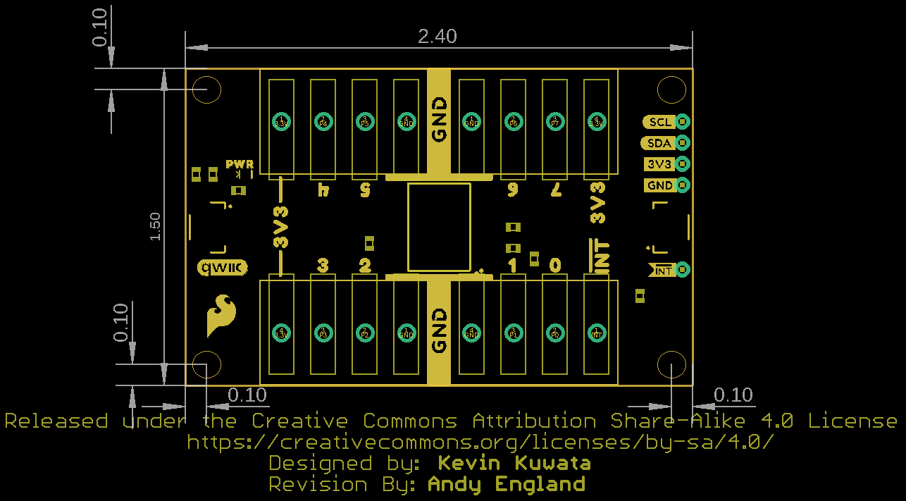
 Schematic
 Datasheet (TCA9534)
Product Overview
Do you find yourself wishing that you had just a few more GPIO pins? What if you only need that one more pin? You could add another microcontroller to your project but that increases cost and complexity. Instead, you can use the Qwiic GPIO to add eight new pins to your Qwiic project!
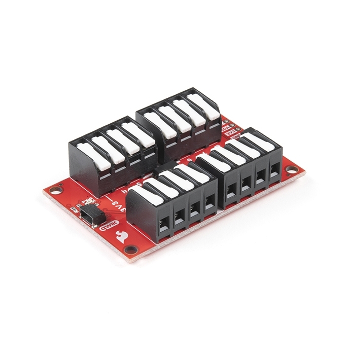
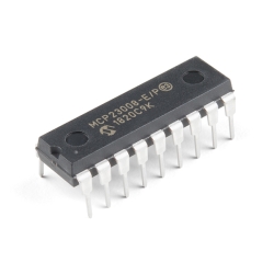
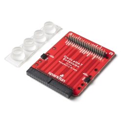
The Sparkfun Qwiic GPIO is an I²C device based around the TCA9534 I/O Expander IC from Texas Instruments. The board adds an additional eight IO pins which you can read and write just like any other digital pin on your controller. The details of the I²C interface have been taken care of in an Arduino library so you can call functions similar to Arduino's pinMode and digitalWrite, allowing you to focus on your creation!
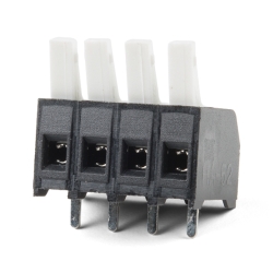
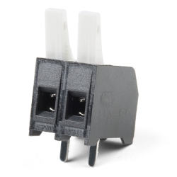
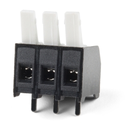
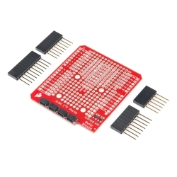
The TCA9534's pins are broken out to easy-to-use latch terminals; never screw another wire into place! The terminals are relatively roomy themselves, so feel free to latch multiple wires into a ground or power terminal. With three customizable address jumpers, you can have up to eight Qwiic GPIO boards to be connected on a single bus allowing upwards of 64 additional GPIO pins! The default I²C is 0x27 and can be changed by adjusting the jumpers on the back of the board.


Features & Specs
Documentation
Customer Reviews

Stock and Customer Discounts
Available Discounts
- $6.41 | 10+ units
- $6.08 | 25+ units
- $5.74 | 100+ units