- Home
- Product Categories
- Memory Cards
- SparkFun SD/MMC Card Breakout

SparkFun SD/MMC Card Breakout
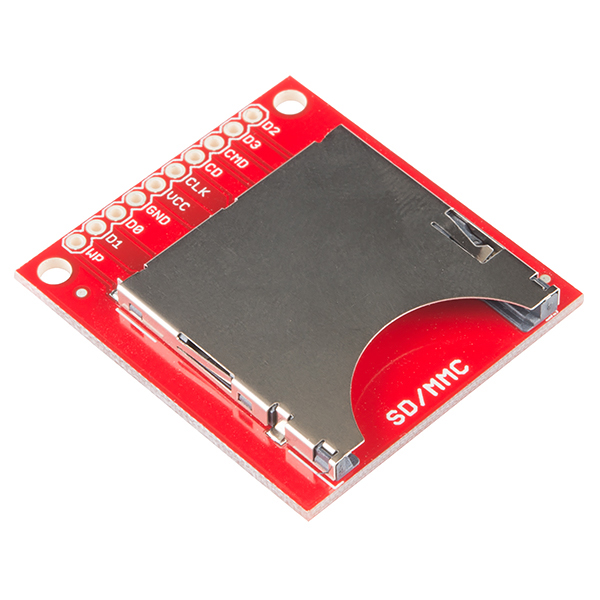
With SD and MMC memory prices dropping, the time is right for mass storage and datalogging. This breakout board will allow you to breakout the SD/MMC socket to a standard .1" 10-pin header. Perfect for breadboarding and the likes. Board comes fully assembled and tested as shown.
- 1.3" x 1.5"
- Schematic
- Eagle Files
- Datasheet (SD/MMC Socket)
- Hookup Guide
- Example MMC Interface Code
- GitHub (Design Files)
SparkFun SD/MMC Card Breakout Product Help and Resources
MicroSD Shield and SD Breakout Hookup Guide
March 25, 2015
Adding external storage in the form of an SD or microSD card can be a great addition to any project. Learn how in this hookup guide for the microSD shield and SD breakout boards.
Additional Tutorials
Here are a few other tutorials that might be helpful:
http://arduino-info.wikispaces.com/SD-Cards
http://elasticsheep.com/2010/01/reading-an-sd-card-with-an-atmega168/
http://opengears.blogspot.com/2012/01/cheap-diy-sd-card-breakout-board-for.html
Logic Levels and Connections
You must bring the voltage down from a 5V Arduino with a logic level converter. If you don't have a logic level converter, you can use some resistors like the ones that were used in our old logic level converter https://learn.sparkfun.com/tutorials/using-the-logic-level-converter#hardware-overview. To use with Arduino, there is an SD card library that has already been written => http://arduino.cc/en/Reference/SD.
Note: In relation to the SD Mode http://pinouts.ru/Memory/sdcard_pinout.shtml and the pins of this breakout:
- CS/SS should be connected to CD/DAT3, which is labeled as D3
- MISO should be connected to DAT0 which is labeled D0
- MOSI should be connected to CMD which is labeled as CMD on the board
We also have a tutorial using the microSD Shield that might be of some use => https://learn.sparkfun.com/tutorials/microsd-shield-and-sd-breakout-hookup-guide. Try looking at the design of the microSD shield to connect to an Arduino Uno footprint. There are other widgets on our storefront that use the microSD (like the OpenLog or LilyPad MP3 to name a few). Try looking at the Eagle board layouts and schematics for an idea of how to connect a microcontroller to the SD and microSD cards.
Core Skill: Soldering
This skill defines how difficult the soldering is on a particular product. It might be a couple simple solder joints, or require special reflow tools.
Skill Level: Noob - Some basic soldering is required, but it is limited to a just a few pins, basic through-hole soldering, and couple (if any) polarized components. A basic soldering iron is all you should need.
See all skill levels
Comments
Looking for answers to technical questions?
We welcome your comments and suggestions below. However, if you are looking for solutions to technical questions please see our Technical Assistance page.
Customer Reviews
4 out of 5
Based on 3 ratings:
0 of 1 found this helpful:
good
good
This works fine for a barebones board
but I wish the board included pullup resistors, which are recommended for all SD/MMC card circuits.
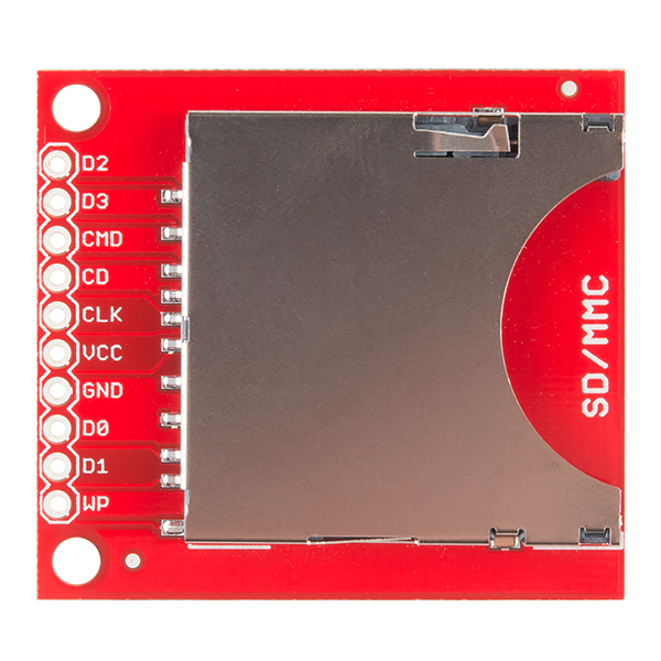
It is late and I am very tired. If this is obvious I'm not getting it. For the life of me I can't decipher the pin out to sd card / spi on the breakout. From the upper left (card goes in in the right) they are labeled
D2 D3 CMD CD CLK VCC GND D0 D1 WP
I want to hook this up to a spi bus device (mbed) and I get the VCC, GND, CLK but which ones are:
SPI mosi SPI miso CS
We are also struggling finding the CS, like DaddyOh has reported :/
Please help
Mounting holes are always good.
I would like a sanity check on my circuit as I have not gotten this sd card reader to work. I have wired it as such http://imgur.com/f7ryror using pull down resistors to bring I/O and power down to 3.3V and am using the following code with the pin changed to pin 10 http://arduino.cc/en/Tutorial/CardInfo , yet I still get SD library initialization failed. Anyone have any suggestions?
Do I need to add anything to this or can I wire it directly to my microprocessor board? I know normally there are some pull up/down resistors.
Yeah you may need some resistors on the SPI lines actually. I would recommend "SD Card Projects Using the PIC Microcontroller" by Dogan Ibrahim. He walks you through a variety of different projects, near the end he has a data logging project. Even if you're not using a PIC, it may still be worth a look so that you know what to be cognizant of with your circuit.
Does it make a difference if I'm using an STM32F4 to drive it? I won't bit bang, I'll be using the SDIO hardware feature of the chip? I have internal resistors, they're not strong enough?
I've been working with SD cards for a long time now using this chip. But they've always been on the same board.
I'm not sure about the STM32F4, as long as it has some type of SPI module, you should be fine.
But internal resistors will not be strong enough, here's a promising webpage I found about SD cards and PIC projects. Even if you're using a diff mcu (microcontroller) the main takeaways are the same (1) use a library to comm with the SD card and (2) have some resistors on the lines from your mcu to the SD card. This is the link: http://www.studentcompanion.co.za/post/2013/09/29/Interfacing-SD-Card-With-PIC-Microcontroller-MikroC
I'll try it and report back. That link seemed to say they needed the resistors because their IO logic pins were ~4v. Stm32 is 3.3v :)
STM32F4 needed the resistors, but it works great! I'm driving it with a Cerb40 II board from GHI.
It's just the bare socket. All the interface stuff is your problem.