MIKROE LED Driver 12 Click
LED Driver 12 Click is a compact add-on board that simplifies the control of multiple LEDs.
Product Overview
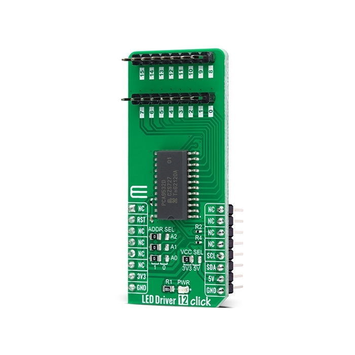
LED Driver 12 Click is a compact add-on board that simplifies the control of multiple LEDs. This board features the PCA9532, a 16-bit I2C-configurable I/O expander optimized for dimming LEDs in 256 discrete Red/Green/Blue (RGB) steps from NXP Semiconductors. The PCA9532 offers high efficiency, supporting up to 16 LED channels and delivering a maximum of up to 25mA of LED current per channel. It contains an internal oscillator with two user-programmable blink rates and duty cycles coupled to the output PWM. Any bits not used for controlling the LEDs can be used for GPIO expansion, which provides a simple solution when additional I/O is needed for some sensors, push-buttons, or alarm monitoring. This Click board™ is suitable for color mixing and backlight application for amusement products, LED status signalization, home automation projects, and many more.
LED Driver 12 Click is supported by a mikroSDK compliant library, which includes functions that simplify software development.
LED Driver 12 Click as its foundation uses the PCA9532, a 16-bit I2C-configurable LED dimmer from NXP Semiconductors. The PCA9532 has two fully programmable PWM controllers used to control up to 16 LED channels, switching each of the LEDs ON and OFF independently. Each LED output, 16 LED drivers presented on two 1x8 male headers, with a maximum output current of 25mA per channel, has a programmable period ranging from 0.6Hz to 152Hz and a programmable duty cycle from 0 to 100%, which means that the LEDs can be set to blink steadily and visibly, or dimmed.
Any bits not used for controlling the LED channels can be used for General Purpose parallel Input/Output (GPIO) expansion, providing a simple solution when additional I/O is needed for some power switches, sensors, push-buttons, alarm monitoring, fans, or other applications.
LED Driver 12 Click communicates with MCU using the standard I2C 2-Wire interface that supports Standard-Mode (100 kHz) and Fast-Mode (400 kHz) operation. The PCA9532 has a 7-bit peripheral address with the first five MSBs fixed to 1100. The address pins A0, A1, and A2, are programmed by the user and determine the value of the last three LSBs of the peripheral address, which can be selected by onboard SMD jumpers labeled as ADDR SEL allowing selection of the peripheral address LSBs.
Alongside the internal Power-On Reset (POR) function, this board also has an active-low reset signal routed on the RST pin of the mikroBUS™ socket used to recover from a bus-fault condition. When this signal is asserted low, the PCA9532 resets its registers alongside with I2C state machine and deselects all channels.
This Click board™ can operate with both 3.3V and 5V logic voltage levels selected via the VCC SEL jumper. This way, it is allowed for both 3.3V and 5V capable MCUs to use the communication lines properly. However, the Click board™ comes equipped with a library containing easy-to-use functions and an example code that can be used, as a reference, for further development.


Features & Specs
- Interface: I2C
- Compatibility: mikroBUS™
- Dimensions: 57.15 x 25.4mm
- Input Voltage: 3.3V or 5V
- Maximum Output Current: 25 mA
- Operating Temperature Range: Min. -40°C, Typ. +25°C, Max. +85°C
Documentation
Customer Reviews

Stock and Customer Discounts
Available Discounts
- $18.00 | 25+ units
- $17.06 | 100+ units