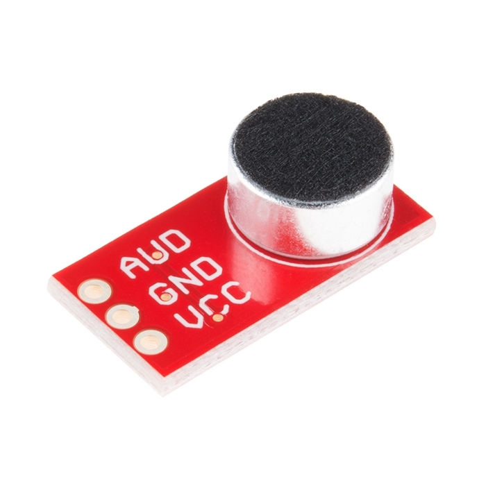
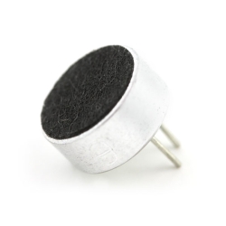
Breakout Board for Electret Microphone

Replacement:BOB-09964. The new version has a few small value changes. This page is for reference only.

Ready to add audio to your next project? This small breakout board couples a small electret microphone with a 100x opamp to amplify the sounds of voice, door knocks, etc loud enough to be picked up by a microcontrollers Analog to Digital converter. Unit comes fully assembled as shown. Works from 2.7V up to 5.5V.

Breakout Board for Electret Microphone Product Help and Resources

Dot/Bar Display Driver Hookup Guide

January 16, 2014

How to hook up the LM3914 or LM3916 to drive a 10-LED display with a lone analog signal.

Electret Mic Breakout Board Hookup Guide

June 23, 2016

An introduction to working with the Electret Mic Breakout Board.

Comments

Looking for answers to technical questions?

We welcome your comments and suggestions below. However, if you are looking for solutions to technical questions please see our Technical Assistance page.

  • Tinkerish / about 16 years ago / 2

    I am using this microphone module in my audio spectrum display project here:
    http://tinkerish.com/blog/?p=39

  • mellomutt / about 14 years ago / 1

    Like others here, I found that the wiring guide they offer above simply does NOT work. BUT, I put a 5k resistor coming off the ground and now it DOES. I'm using the Arduino Mega2560.

    • bernieke / about 9 years ago / 1

      Hi, could you explain where exactly you put the 5k resistor? I finally got around to start working on my sensors (after five years...), and am not getting any usable output.

  • Blue Hair Bob / about 14 years ago / 1

    I am measuring 2.5V on this when the room is quiet and no change when noisy. Any ideas what is going on?

  • sery / about 15 years ago / 1

    Switch your voltmeter to ACV to measure the output voltage.

  • Engel / about 15 years ago / 1

    I hooked up the breakout to a 5V source and only see about 10mVpp on the O-Scope when speaking loudly next to the mic. Is there something special I need to be doing to get a better signal?
    Thanks for any help.

    • Engel / about 15 years ago / 1

      I got it working, not sure what the problem was but we are now seeing between 500mVpp to 1Vpp on the OScope. We are trying to amplify it to 5V, but are unable to get an op-amp to output anything with the audio signal as input.
      Any suggestions?

  • With 5V VCC, I measured about 0.5V p-p max for loud speech next to the microphone. People seem to expect ~5V p-p, so the gain's about a factor of 10 too low. One solution is to use the AVR/Arduino's internal 1.1V reference, and AC couple the microphone signal on a ~.6V bias. Warning, ASCII art:
    5V VCC
    ^
    |
    /
    \ 9k
    /
    \
    |
    +---||--- Audio in
    | 1uF
    +---------- AIN0 to Arduino
    |
    /
    \ 1k
    /
    \
    |
    v
    GND
    Another solution is just to add an op-amp for additional gain.
    Sparkfun: if you redo this board, I think the .1uF bypass capacitor on the input should be 1uF instead, to give a high-pass cutoff of ~150Hz, instead of the present 1.5kHz.

    • I ended up (a) adding an extra 1uF capacitor across C1 (optional, improves low-end response), and (b) using an LM386 amplifier on the output to get up to ~5V p-p. I used the "minimum parts count, gain of 20" circuit from the LM386 datasheet exactly (http://www.national.com/mpf/LM/LM386.html), except that I added a 1uF capacitor in series between the Mic breakout board and the input to the LM386, for AC coupling. You can then adjust the potentiometer at the input to dial in the gain -- just be careful, if it is set too high the circuit will oscillate.

      • N8B / about 14 years ago / 1

        I did a rev of this amp so that the roll off issue amp and the loading issue on the mic is gone. The revision should be on the website within the next week or so.

        • Member #38182 / about 12 years ago / 1

          DO you have this rev posted, would like to see it. Ron

  • oalbrecht / about 15 years ago / 1

    I tried using this mic and putting it into an arudio via analogRead(). It did not work and only gave me values in the 500s if I attached Vcc to 5 V and in the 300s if I attached Vcc to 3.3V. No matter what sound I made, it didn't give me any responses. Can someone please help me? Thanks!!

    • mellomutt / about 14 years ago / 1

      I had the same problem until I put a 5k resistor coming off the ground.

  • ThinkerT / about 15 years ago / 1

    Would you be able to use the analogRead() function on Arduino to record on the microphone?
    Thanks

  • Jagrolet / about 15 years ago / 1

    Unless the mic is very close to the source, the output is almost unusable. It takes a pretty good finger snap or hand clap to get my O-scope to show a response when set on 1VPP. It would be nice if you could easily adjust the gain, however the small smt components and tight layout make this a bit challanging.

  • baldengineer / about 15 years ago / 1

    When using this module, I am seeing a (1.5Vpp) pulse every 13.6ms (73.5Hz). This pulse appears to only occurs if there isn't enough sound going into the mic. Could this be some kind of oscillation from the op amp? With this periodic pulse, I am having a difficulty determining when there is actual sound coming in or not.
    Also, if I don't put the mic right next to the sound source, I get almost no (usable) output...

    • mellomutt / about 14 years ago / 1

      I had the same problem until I put a 5k resistor coming off the ground.

Customer Reviews

No reviews yet.