SparkFun XBee Explorer Regulated
Helpful Documentation
 Schematic
Product Overview
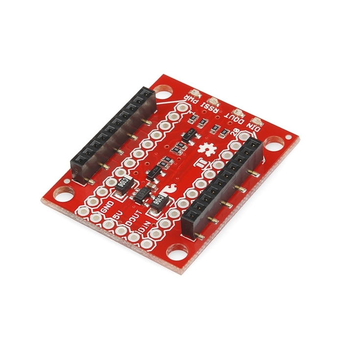
The SparkFun XBee Explorer Regulated takes care of the 3.3V regulation, signal conditioning, and basic activity indicators (Power, RSSI and DIN/DOUT activity LEDs). It translates the 5V serial signals to 3.3V so that you can connect a 5V (down to 3.3V) system to any XBee module. The board was conveniently designed to mate directly with the SparkFun Arduino Pro series of boards for wireless bootloading and USB based configuration.
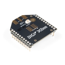
This unit works with all XBee modules including the Series 1 and 2, standard and Pro versions. Plug an XBee into this breakout and you will have direct access to the serial and programming pins on the XBee unit and will be able to power the XBee with 5V.
This board comes fully populated with 3.3V regulator (5V max input), XBee socket, four status LEDs, and level shifting. In the latest revision the diode level shifter is replaced with a more robust MOSFET level shifter. This board does not include and XBee module. XBee modules sold below.
Note: This board cannot source the power required for the Cellular XBee line. It will only work with the 802.15.4 variants.


Documentation
Customer Reviews

Stock and Customer Discounts
Available Discounts
- $13.78 | 10+ units
- $13.05 | 25+ units
- $12.33 | 100+ units