SparkFun Ardumoto - Motor Driver Shield
 Hookup Guide
 Schematic
 Datasheet
Product Overview
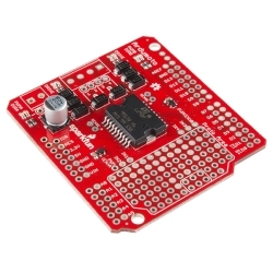
The Ardumoto Shield is a dual-motor controller for Arduino. Based on the L298 H-bridge, the SparkFun Ardumoto can drive two DC motors up to 2A per channel. Combined with an Arduino, the Ardumoto makes a fantastic controller platform for RC vehicles or even small autonomous robots. It’s now easier to use, featuring control signal LEDs, while also being much more flexible for advanced users.
The board takes its power from the same Vin line as the Arduino board and includes blue and yellow LEDs to indicate active direction. All driver lines are diode protected from back EMF. The L298 is a two-channel motor driver, which means it can individually drive up to two motors, making it perfect for a two-wheel-drive vehicle. Each channel on the L298 can deliver up to 2A to the motor to which it’s connected. Keep in mind, though, that the amount of current available to your motor also depends on your system’s power source.
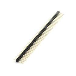
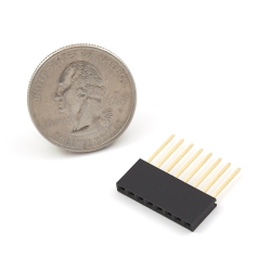
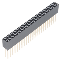
Note: The Ardumoto does not include screw terminals or stackable headers; you will need to purchase both separately. You can find them in the aforementioned links or in the Recommended Products below.
Documents:


Documentation
Customer Reviews