Bus Pirate - v3.6a
Helpful Documentation
 Hookup Guide
 Schematic
Product Overview
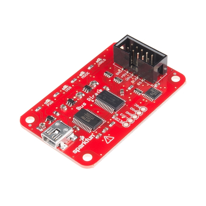
The Bus Pirate v3.6a, created by Ian Lesnet, is a troubleshooting tool that communicates between a PC and any embedded device over 1-wire, 2-wire, 3-wire, UART, I2C, SPI, and HD44780 LCD protocols - all at voltages from 0-5.5VDC. This product eliminates a ton of early prototyping effort when working with new or unknown chips.
Working with the Bus Pirate is simple and effective - type commands into a terminal on your computer, those commands are interpreted by the Bus Pirate and sent via the proper protocol. The Pirate will also interpret data sent from your embedded device back to your computer terminal. A big bonus is the bootloader installed on the PIC, which allows you to easily update the firmware and change the functionality of the board.
The main components of the Bus Pirate are the PIC24FJ64 processor and a FT232RL USB-to-Serial chip. A Mini-B USB connector that has also been populated on the board, provides the power to the Bus Pirate and allows you to interact with via your PC. The major difference in this version of the Bus Pirate comes from the shrouded 0.1" pitch 2x5 pin header, which has been flipped around to help standardize this board. Additionally every pin on this header has been labeled, eliminating the need for a separate I/O pin description document like with earlier versions.
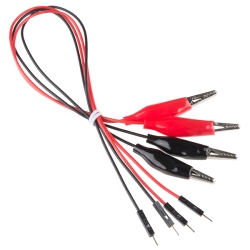
Note: We sell a handy cable to connect the Bus Pirate to the system you are developing, debugging, or reverse engineering.
Note: This product is a collaboration with Ian Lesnet. A portion of each sales goes back to them for product support and continued development.
Features:
- Supported protocols:
- 1-Wire
- I2C
- SPI
- JTAG
- Asynchronous serial
- MIDI
- PC keyboard
- HD44780 LCD
- 2- and 3-wire libraries with bitwise pin control
- Scriptable binary bitbang, 1-Wire, I2C, SPI, and UART modes
- 5.5V tolerant pins
- 6V measurement probe
- 1Hz - 40MHz frequency measurement
- 1kHz - 4MHz pulse-width modulator, frequency generator
- On-board multi-voltage pull-up resistors
- On-board 3.3volt and 5volt power supplies with software reset
- Macros for common operations
- Bus traffic sniffers (SPI, I2C)
- A bootloader for easy firmware updates
- Transparent USB->serial mode
- 10Hz - 1MHz low-speed logic analyzer
- Scriptable from Perl, Python, etc.
- Access to PIC24FJ64 ICSP programming port
Documents:


Features & Specs
- Supported protocols:
- 1-Wire
- I2C
- SPI
- JTAG
- Asynchronous serial
- MIDI
- PC keyboard
- HD44780 LCD
- 2- and 3-wire libraries with bitwise pin control
- Scriptable binary bitbang, 1-Wire, I2C, SPI, and UART modes
- 5.5V tolerant pins
- 6V measurement probe
- 1Hz - 40MHz frequency measurement
- 1kHz - 4MHz pulse-width modulator, frequency generator
- On-board multi-voltage pull-up resistors
- On-board 3.3volt and 5volt power supplies with software reset
- Macros for common operations
- Bus traffic sniffers (SPI, I2C)
- A bootloader for easy firmware updates
- Transparent USB->serial mode
- 10Hz - 1MHz low-speed logic analyzer
- Scriptable from Perl, Python, etc.
- Access to PIC24FJ64 ICSP programming port
Documentation
Customer Reviews

Stock and Customer Discounts
Available Discounts
- $38.73 | 10+ units
- $36.69 | 25+ units
- $34.65 | 100+ units