SparkFun Electret Microphone Breakout
BOB-12758
SparkFun Electret Microphone Breakout
SKU: BOB-12758
$8.50
In stock
SKU
BOB-12758
Helpful Documentation
 Hookup Guide
 Schematic
 Datasheet (OPA344)
Product Overview
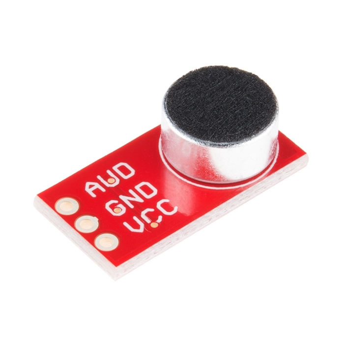
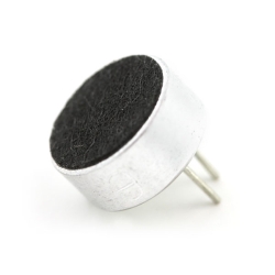
This small breakout board couples an Electret microphone (100Hz--10kHz) with a 60x mic preamplifier to amplify the sounds of voice, claps, door knocks or any sounds loud enough to be picked up by a microcontroller’s analog-to-digital converter. Each breakout comes fully assembled and works from 2.7V up to 5.5V.
The Electret Mic Breakout translates amplitude (not volume) by capturing sound waves between two conducting plates (one a vibrating diaphragm and the other fixed) in the microphone and converting them into electrical waves. These electrical signals are then amplified and picked up by your microcontroller’s ADC.
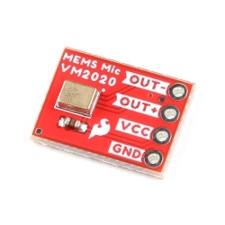
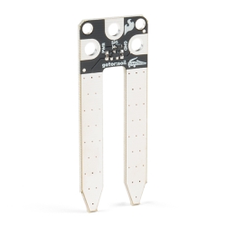
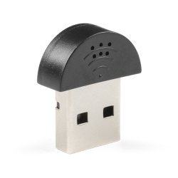
Similar Items


Hookup Accessories


Documentation
- Schematic
- Eagle Files
- Hookup Guide
- Datasheet (OPA344)
- Datasheet (Mic)
- GitHub
Customer Reviews

SparkFun Electret Microphone Breakout
$8.50
BOB-12758