


 PJRC Bootloader Chip Page
Product Overview
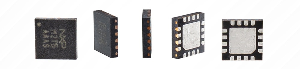
The Teensy T3 Bootloader Chip (IC_MKL02Z32_QFN16) is the essential component for building a custom PCB compatible with the Teensyduino and Teensy Loader ecosystem. Instead of embedding an entire development board into your final project or production run, you can pair this pre-programmed QFN16 IC with a supported blank NXP Kinetis microcontroller on your own circuit board. The bootloader automatically detects the main processor you connect and configures your custom hardware to operate as a Teensy LC, Teensy 3.2, Teensy 3.5, or Teensy 3.6.
These chips are shipped as uncut reels containing 500 Teensy T3 Bootloader Chips. This bulk packaging is the most economical solution for large-scale production runs, manufacturing custom Teensy-powered boards, and contract manufacturing supply. If you're looking for quantities in the 1-499 range, consider picking up chips in cut tape instead.
Custom PCB Integration Requirements
Because the Teensy T3 Bootloader Chip acts as the bridge between the Teensy software environment and blank off-the-shelf silicon, your custom board design will need to pair it with specific external hardware to form a working system:
- Automatic Model Detection: Supports blank NXP Kinetis microcontrollers and automatically configures the board identity. Pair it with an MKL26Z64VFT4 for Teensy LC, an MK20DX256VLH7 for Teensy 3.2, an MK64FX512VMD12 (or LQFP MK64FX512VLQ12) for Teensy 3.5, or an MK66FX1M0VMD18 (or LQFP MK66FX1M0VLQ18) for Teensy 3.6.
- Crystal Oscillator Requirements: Requires a 16MHz crystal rated for an 8pF to 10pF parallel load capacitance placed close to the target MCU with a dedicated ground plane underneath (if using an 18pF rated crystal, add two 20pF capacitors to the design).
- Critical Power Routing: Both
VREGOUTandVBATon the target microcontroller will need to be connected to 3.3V power even if you're bypassing the internal voltage regulator or Real-Time Clock (RTC). The internal USB transceiver and boot sequence depend on these rails. - First-Time Programming & NMI Pin: A completely blank target processor requires a physical press of the Program pushbutton (or pulling the Program pin to ground) for its very first upload. Additionally, the target MCU's
PTA4pin defaults to a Non-Maskable Interrupt (NMI) when blank and must be left floating or pulled high until the first code upload disables the NMI function.
Footprint & Hardware Debugging
The T3 Bootloader Chip connects to your target processor using a minimal set of programming, reset, and debug lines, leaving unused pins unconnected. The chip also supports external hardware debugging setups via the PTA3 pin. Pulling PTA3 low tri-states the MKL02's signals and ignores the Program line, allowing an external debug adapter to take full control of the target microcontroller.
