- Home
- Product Categories
- Relay
- SparkFun Beefcake Relay Control Kit (Ver. 2.0)

SparkFun Beefcake Relay Control Kit (Ver. 2.0)
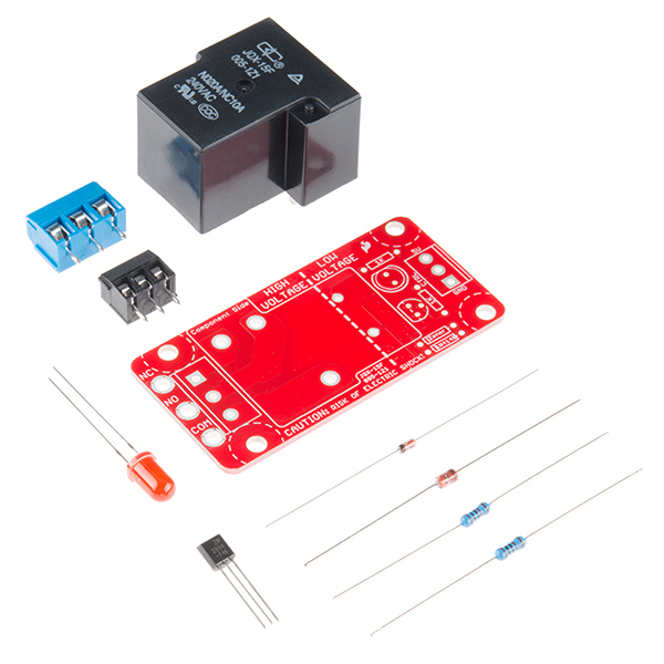
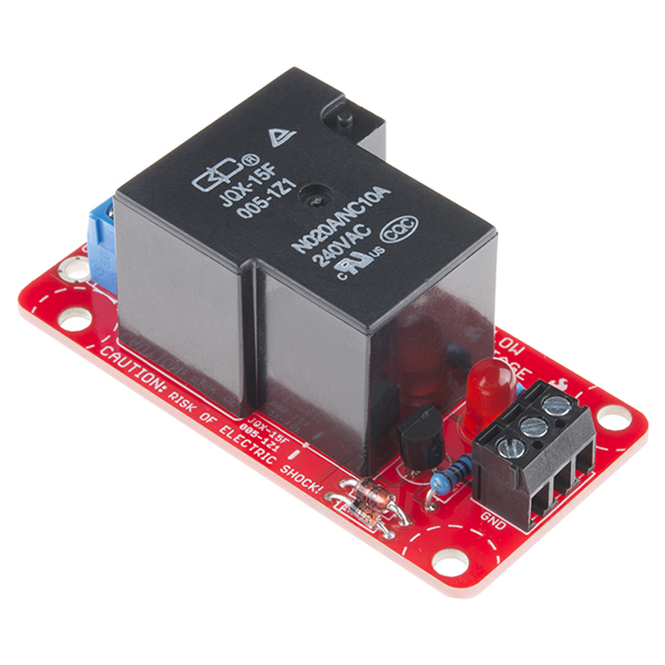
Your 5V system can wield great power with this big, beefy relay board. How does 10A on the NC contacts and 20A on the NO contacts at 220VAC sound? The SparkFun Beefcake Relay Control Kit contains all the parts you need to get your high-power load under control. Only minimal assembly is required!
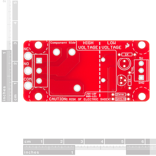
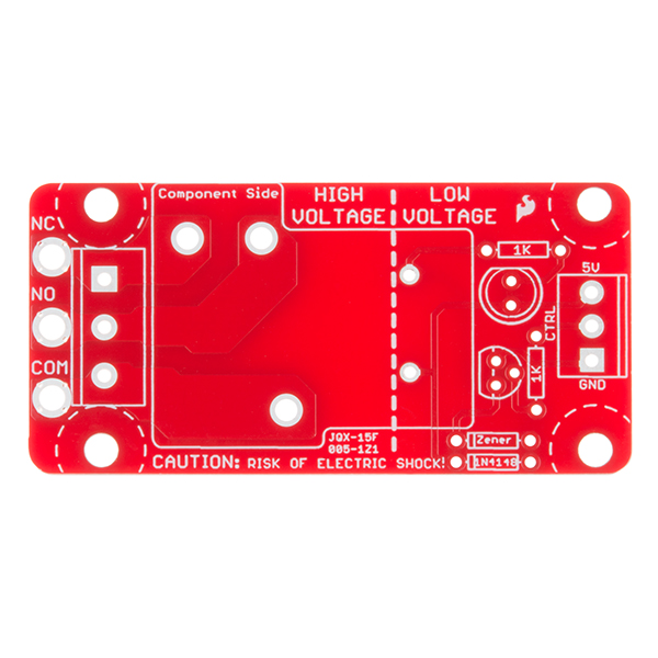
The heart of the board is a sealed, SPDT 20A/10A Relay. The relay is controlled by 5V logic through a transistor, and an LED tells you when the relay is closed. This is a kit, so it comes as through-hole parts with assembly required, which makes for some nice soldering practice. Screw terminal connectors on either side of the board make it easy to incorporate into your project.
There are some pretty beefy traces connecting the relay to the load pins, but the 3-pin terminals are only rated for 15A max! If you plan on connecting a larger load, you'll need to solder directly to the board. As always with high current and voltage, play it safe and use your judgment when deciding how much of a load you want to put on a board -- in open airflow the PCB can handle the full 20A for a few minutes at a time, but in an enclosed area heat can build up.
Note: Please keep in mind that this board is really meant for someone with experience and good knowledge of electricity. If you're uncomfortable soldering or dealing with high voltage, please check out the IoT Power Relay. The IoT Power Relay is fully enclosed, making it a lot safer.
- Voltage Rating: 220VAC/28VDC
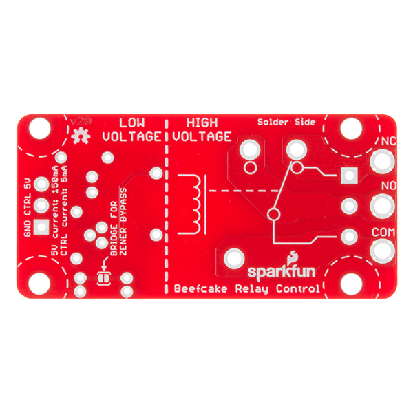
- VCC requirements: 4-6V, 150mA capable
- SPDT pins exposed (Form C)
- 14 AWG screw terminals for relay connections.
- 10 AWG solder lugs for relay connections.
- Flyback diode included
- Zener recovery diode included (decreases turn-off time)
- Heavy 2 oz. copper on PCB
- Schematic
- Eagle Files
- Hookup Guide
- Datasheet (JQX-15F/005-1Z1)
- Relay Tutorial
- GitHub
SparkFun Beefcake Relay Control Kit (Ver. 2.0) Product Help and Resources
Beefcake Relay Control Hookup Guide
June 2, 2016
This is a guide for assembling and basic use of the Beefcake Relay Control board
How to Build a Remote Kill Switch
May 31, 2016
Learn how to build a wireless controller to kill power when things go... sentient.
Photon Remote Water Level Sensor
June 2, 2016
Learn how to build a remote water level sensor for a water storage tank and how to automate a pump based off the readings!
ESP8266 Powered Propane Poofer
March 15, 2016
Learn how Nick Poole built a WiFi controlled fire-cannon using the ESP8266 Thing Dev Board!
Core Skill: Soldering
This skill defines how difficult the soldering is on a particular product. It might be a couple simple solder joints, or require special reflow tools.
Skill Level: Rookie - The number of pins increases, and you will have to determine polarity of components and some of the components might be a bit trickier or close together. You might need solder wick or flux.
See all skill levels
Core Skill: DIY
Whether it's for assembling a kit, hacking an enclosure, or creating your own parts; the DIY skill is all about knowing how to use tools and the techniques associated with them.
Skill Level: Noob - Basic assembly is required. You may need to provide your own basic tools like a screwdriver, hammer or scissors. Power tools or custom parts are not required. Instructions will be included and easy to follow. Sewing may be required, but only with included patterns.
See all skill levels
Core Skill: Electrical Prototyping
If it requires power, you need to know how much, what all the pins do, and how to hook it up. You may need to reference datasheets, schematics, and know the ins and outs of electronics.
Skill Level: Competent - You will be required to reference a datasheet or schematic to know how to use a component. Your knowledge of a datasheet will only require basic features like power requirements, pinouts, or communications type. Also, you may need a power supply that?s greater than 12V or more than 1A worth of current.
See all skill levels
Comments
Looking for answers to technical questions?
We welcome your comments and suggestions below. However, if you are looking for solutions to technical questions please see our Technical Assistance page.
Customer Reviews
4.5 out of 5
Based on 22 ratings:
3 of 3 found this helpful:
good board, 3.3v CTRL needs 660 ohm resistor
Seconding Member #380262's note: To control this with 3.3v, R2 needs to be switched to 660 ohm or so.
I built two of these, one works pretty reliably on 3.3v, but the other one doesn't fully close, rather than a crisp click it made a soft blip sound. Switching the resistor fixed it (I used a 680 ohm).
Also I had 110V AC going through that, and before I fixed it I was getting ~60V NO and ~20V on NC. Seems it was somehow half closed, and possibly arcing inside the relay?, which could be a dangerous failure mode.
7 of 7 found this helpful:
Excellent relay
Works great and is as advertised. However I would add if you are using a RPi to control this (3.3v) then change the gate resistor to 660 ohms so that the current stays above 5mA and will properly trigger the transistor.
1 of 1 found this helpful:
Excellent kit
I purchased 3 beefcake relay kits for a water control project. Two of them were exactly as advertised, but the third was missing one 1k resistor and had an extra transistor. I used a 1k from my junk box and completed the kit. They will be operating in a humid environment so durability remains to be established. I used two soldering irons - a small one for the low voltage side and a big one for the relay pins.
1 of 1 found this helpful:
This is a pretty nice little relay board.
I have several projects where I need to be able to turn larger pieces of equipment on and off and I've been making my own relay controllers but these little kits put everything together in one nice package and the price it good. I haven't had mine in service for long so I'll re-post if I have any problems in the future, but so far so good. The LED is a nice addition. My only concern is that people could shock the crap out of themselves if this isn't properly enclosed in a box. But then again, that's what makes it fun right?
wicked cool
i just now finished soldering the kit together. purpose: to switch a DC motor which is actually a fountain pump, using the Arduino. the fountain pump is for a hydroponics grow-tower, so, using the "blink" sketch with the delay set to 1-million (about 16-ish minutes) that gives the plants 16 minutes on, 16 minutes off, of hydroponic solution. it's sitting beside me as i type this and is working perfectly! thanks guys!
Just what I needed.
Easy to solder together and assemble. Have three running off an Arduino Uno to cycle power to different sensors for testing. Works great.
These things are awesome
Easy to assemble and fairly cheap. I have 10 of them in use in my swimming pool control system.
Keep on ticking
Using four of them with an Arduino to do some testing, over 200,000 cycles (in less than two weeks) on each one with no problem! Cheap, easy to use, and reliable - what else could you ask for?
Only feedback would be that if they are ever revisioned, it would be nice if they added ability to use a 0.1" header for the inputs...
Love it!
I love this product and have used many of them. I especially like the new version with both NO and NC terminals. I don't have to modify the board for some of the applications.
Great Relay!
I am building a 14 zone irrigation system for my yard/garden beds/potted plants and this relay is the key to the project. Works great!
Best I seen so far
They look like they are built to handle the rated load. Good heavy traces. Others I have seen online can't hold up. Good design folks.
What what I needed...
Certainly more compact than 4 "power switch tails"
https://photos.app.goo.gl/YX9eifOCKnh42arC2
good, but voltage leaking
pretty easy to put together, but after i put it in my system i noticed that on the normally open terminal that it's "leaking" 3 volts for some reason on an input of 120 volts. not sure why, because if it's open then it should read 0 volts, right? ;-)
maybe i goofed up somehow, but it's puzzling. anyway, i'd still recommend it because there isn't anything that i know of that an integrated relay that can handle this much load.
Hello, and thanks for the review!
Relays shouldn't leak at all. You might try cleaning any flux residue off the bottom of your board around the relay and output connector. A bit of flux there could definitely cause a small current leak.
Very convenient, but....
I've had several of these work without issue when driven by a 3.3 Vdc control. However, others have proven to not operate fully. I've had to replace the 1K resistor with a 470 ohm resistor to get a solid relay energize. I'd suggest Sparkfun include a 470 ohm resistor for the control (to the transistor base) for those instances where 3.3 Vdc will be used for control with a corresponding mention in the documentation.
I'm super happy with it!
Assembly and soldering was a snap, and it works just like it's supposed to. This thing can handle an impressive amount of current, though I'm currently using it at only a fraction of it's rated capacity to turn off a bunch of lights in my bedroom. Would def recommend!
Works as advertised, good value for money
Basic electromechanical relay board, quick to solder together and works as you would expect. I'm using it to switch a 115VAC outlet that has a load of about 7 amps connected. Power is normally "on", so power is wired through the normally closed contacts. Power is only disconnected for a few seconds at a time to cycle power on the load once every few days so I expect it to last for quite a while.
Aquaponic System Heater
Handles the 2kW water heater element. Other relays... didn't!
Work great (if you don't mix up the diodes).
I've used these in my brewery controller for years. They happily switch and carry 240V/10A on the high voltage side.
However I had one relay that MOSTLY worked but had a weird failure mode that it would regularly drop into halfway through a brew day. It was driving me nuts and I thought I'd finally fixed it many times, only to have the issues resurface shortly after.
So I finally gave up on it and bought a replacement, and when I swapped it out, I noticed that I had got the signal and Zener diodes mixed up on the dodgy board when I assembled it. It was a relief to finally understand what had been going on, but yeah, don't do that.
Amazing Kit
The Beefcake Relay Control Kit (Ver. 2.0) Is an amazing kit. It is easy to assemble and works wonderfully. It works great with the Arduino and the Raspberry Pi.
Easy to assembly and cost effective
I would strongly recommend using this relay (same footprint) with this PCB. It gives you proper spade terminals for the high current connections. I have replaced so many of these relays in different devices because they overloaded the bottom pins on the relay.
http://www.digikey.com/product-detail/en/JTN1AS-TMP-F-DC5V/255-1487-ND/303481
Hi! What are the differences between this and the previous version?
What meljr says, plus better isolation between the high voltage and low voltage sides of the board and this version uses thicker traces (more copper) to increase the current carrying capability.
I have an earlier version. The biggest difference I see is that on the output (hi voltage) side, there are now three connections, a common with normally closed and normally open outputs. The previous version only had the common connection with a single output. This new configuration seems to be much more flexible and allows for an either/or situation with two downstream outputs you want to control. I'm going to order a few.
Any enclosure that fits this kit nicely? I'd like to make something isolated and inline for a power cable ideally. Like the retired https://www.sparkfun.com/products/retired/12920
In case anyone is interested, I made a 3D printed case that will let you mount this relay inline in a power cord. You can find the details here.
How many relays can i hookup to one arduino?
Can someone please comment on the dimensions of this once it is assembled?
1.2 x 2.45 inch base, 1.0 inch height
Love this offering, especially with the three terminal output. How do I tell which is the zener and which is the flyback diode? I'm assuming the smaller one is the 1N4148.
Thanks! It's super useful. Check out the hookup guide -- there are some pictures of the assembly. The diodes also have numbers written on them as well, 1N4148 would be marked:
41
48
Why use this over a solid-state relay? The latter is two bucks more expensive, but needs a lot less power to drive and switches the load on zero crossings. The only thing this one has going is that it has on NC and one NO contact, but how often do you switch between two loads?
How can i hook this one on a board with only 3.3V ? I can get 12V, can i do that?
Could I use this with a 3.3V device like an ESP8266?
3.3 volts on the CTRL pin is definitely enough to cause the relay to trigger. 3.3 volts on the 5V may not be enough to reliably power the coil in the relay though since it's expecting 5 volts. I tested an older version of this product on 3.3 volts and it worked fine, but since it's below spec, you may run into trouble. Give it a shot with 3.3 volts and if you're having trouble, bump the voltage on the 5V pin up to 5 volts and you should be good.
Per product safety (UL60950-1 and UL62368-1), this product appears to meet most requirements for switching 120Vac, but not all; which is commendable and unusual for 'maker' vendors. You people are finally getting better at this, but SF and others should know that you and your ilk were the subject of several discussions at the IEEE Product Safety Engineering Society symposium (last month in Anaheim). The director of OSHA's NRTL program was there and listened with interest, as this stuff has been, as of late, starting to cross from the home workshop to the work-place.
Can you provide some insight as to which 120Vac switching requirements are not met by this product?
Thanks!
Any response would be fraught with legal and technical liabilities. In any case, no reasonable response because intended end-use environment not defined, and installation (O/V) category not specified, and conditions of acceptability not known. But here is a minimal list to start with:
If I use this relay to turn on and off a window blind motor, what protection (for the relay) do I need?
What is the paste brushed on the pcb at the end of assembly in the video?
It's just rubbing alcohol to clean flux off the board.
That looks like some sort of flux removal- water, rubbing alcohol, or possibly some specialized formula. Electronics solder wire (including the one we sell and use in production) will often have a flux core to allow better wetting and flow when you solder your parts in. The residue left after soldering is often a little sticky, slightly conductive, and may eventually corrode your board. It's a good idea to clean the board when you are done, just make sure you let the board dry completely before connecting it to power.