- Home
- Product Categories
- Raspberry Pi Boards
- SparkFun RP2040 mikroBUS Development Board

SparkFun RP2040 mikroBUS Development Board
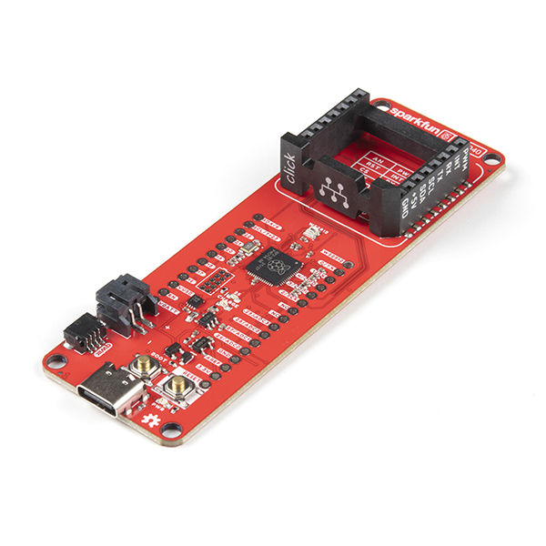
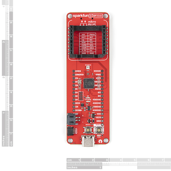
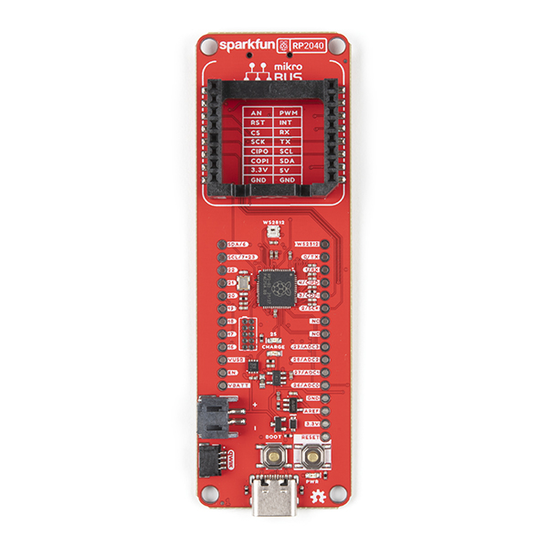
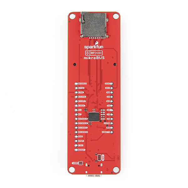
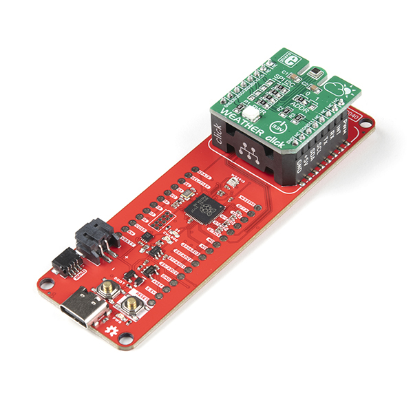
The SparkFun RP2040 mikroBUS Development Board is a low-cost, high performance platform with flexible digital interfaces featuring the Raspberry Pi Foundation's RP2040 microcontroller. Besides the Thing Plus or Feather PTH pin layout, the board also includes a microSD card slot, 16MB (128Mbit) flash memory, a JST single cell battery connector (with a charging circuit and fuel gauge sensor), an addressable WS2812 RGB LED, JTAG PTH pins, four (4-40 screw) mounting holes, our signature Qwiic connectors, and a mikroBUS socket.
The mikroBUS™ standard was developed by MikroElektronika. Similar to our Qwiic and MicroMod interfaces, the mikroBUS socket provides a standardized connection for add-on Click boards™ to be attached to a development board and is comprised of a pair of 8-pin female headers with a standardized pin configuration. The pins consist of three groups of communications pins (SPI, UART and I2C), six additional pins (PWM, Interrupt, Analog input, Reset and Chip select), and two power groups (3.3V and 5V).
The RP2040 is supported with both C/C++ and MicroPython cross-platform development environments, including easy access to runtime debugging. It has UF2 boot and floating-point routines baked into the chip. While the chip has a large amount of internal RAM, the board includes an additional 16MB of external QSPI flash memory to store program code. The RP2040 contains two ARM Cortex-M0+ processors (up to 133MHz) and features:
- 264kB of embedded SRAM in six banks
- 6 dedicated IO for SPI Flash (supporting XIP)
- 30 multifunction GPIO:
- Dedicated hardware for commonly used peripherals
- Programmable IO for extended peripheral support
- Four 12-bit ADC channels with internal temperature sensor (up to 0.5 MSa/s)
- USB 1.1 Host/Device functionality
Note: Please be aware that Qwiic boards and cables, as well as Click boards are not included with the RP2040 mikroBUS Development Board. These parts will need to be purchased separately.
The SparkFun Qwiic Connect System is an ecosystem of I2C sensors, actuators, shields and cables that make prototyping faster and less prone to error. All Qwiic-enabled boards use a common 1mm pitch, 4-pin JST connector. This reduces the amount of required PCB space, and polarized connections mean you can’t hook it up wrong.
SparkFun RP2040 mikroBUS Dev. Board Features
- Raspberry Pi Foundation's RP2040 microcontroller
- Thing Plus (or Feather) Pin Layout:
- 28 PTH Pins
- USB-C Connector:
- USB 1.1 Host/Device functionality
- 2-pin JST Connector for a LiPo Battery (not included):
- 500mA charging circuit
- 4-pin JST Qwiic Connector
- LEDs:
PWR- Red 3.3V power indicatorCHG- Yellow battery charging indicator25- Blue status/test LED (GPIO 25)WS2812- Addressable RGB LED (GPIO 08)
- Buttons:
BootReset
- JTAG PTH Pins
- 16MB QSPI Flash Memory
- µSD Card Slot
- mikroBUS Socket
- Dimensions: 3.7" x 1.2"
- Four Mounting Holes:
- 4-40 screw compatible
RP2040 General Features:
- Dual Cortex M0+ processors, up to 133 MHz
- 264 kB of embedded SRAM in 6 banks
- 6 dedicated IO for QSPI flash, supporting execute in place (XIP)
- 30 programmable IO for extended peripheral support
- SWD interface
- Timer with 4 alarms
- Real time counter (RTC)
- USB 1.1 Host/Device functionality
- Supported programming languages
- MicroPython
- C/C++
1. Note: GPIO 08 is not included in this count, as it passes through the WS2812 addressable RGB LED first. GPIO 07 and GPIO 23 are counted as a single GPIO because they are tied together.↩
2. Note: The GPIO pins are programmable so you can reconfigure the pins! Check out the RP2040 datasheet for more information on the GPIO functionality.↩
- Schematic
- Eagle Files
- Board Dimensions
- Hookup Guide
- Qwiic Info Page
- GitHub Hardware Repository
- Software (SDK) Documentation:
- Online SDK Documentation
- Raspberry Pi Pico C/C++ SDK - A guide on the libraries and tools for C++ development on RP2040 microcontrollers
- Raspberry Pi Pico Python SDK - A guide on the MicroPython environment for RP2040 microcontrollers
- Hardware Component Information:
- Software Development Platforms for the RP2040:
- MicroPython
- Example code to accompany the Get Started with MicroPython on Raspberry Pi Pico book
- Pico C/C++ SDK
- Example codes
- Beta Libraries
- Example code for the beta libraries
- Tools and Resources:
- RP2040 Boot ROM - Source code for the USB mass storage device emulation
- Picotool - Inspecting RP2040 binaries in BOOTSEL mode
- Debugging Probe Configuration
- OpenOCD Debugger
- pico-project-generator - GUI tool to automatically generate a Pico C/C++ SDK project
- UF2 Files- Just drag-and-drop onto your RP2040 board
- C/C++ Files:
- MicroPython Files:
- Utility Files:
microcontroller
- Debugging w/ picoprobe - Debugging with another RP2040 microcontroller
- Reset flash memory - Clears flash memory from board
- MicroPython
SparkFun RP2040 mikroBUS Development Board Product Help and Resources
RP2040 mikroBUS™ Development Board Hookup Guide
March 4, 2022
The RP2040 is the first microcontroller from the Raspberry Pi Foundation. Updated with the new mikroBUS™ socket, the RP2040 development board expands its horizons with a growing ecosystem of +1100 drop-in Click boards™. Click to learn more.
Core Skill: Programming
If a board needs code or communicates somehow, you're going to need to know how to program or interface with it. The programming skill is all about communication and code.
Skill Level: Competent - The toolchain for programming is a bit more complex and will examples may not be explicitly provided for you. You will be required to have a fundamental knowledge of programming and be required to provide your own code. You may need to modify existing libraries or code to work with your specific hardware. Sensor and hardware interfaces will be SPI or I2C.
See all skill levels
Core Skill: Electrical Prototyping
If it requires power, you need to know how much, what all the pins do, and how to hook it up. You may need to reference datasheets, schematics, and know the ins and outs of electronics.
Skill Level: Noob - You don't need to reference a datasheet, but you will need to know basic power requirements.
See all skill levels
Comments
Looking for answers to technical questions?
We welcome your comments and suggestions below. However, if you are looking for solutions to technical questions please see our Technical Assistance page.
Customer Reviews
No reviews yet.
The CS pin on the mikrobus socket is not exposed in the RP2040 Thing Plus. SPI click boards are not usable in CircuitPython using the RP2040 Thing Plus firmware. A new variant is required.