SparkFun Breadboard Power Supply Stick - 5V/3.3V
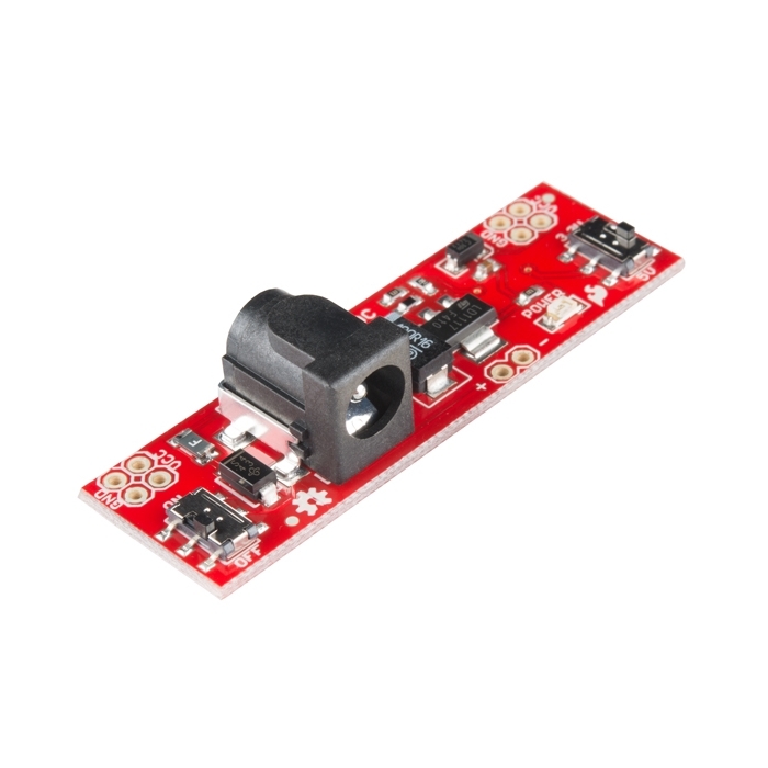
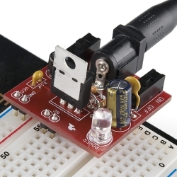
The SparkFun Breadboard Power Supply Stick is a very simple board that takes a 6-12V input voltage and outputs a selectable 5V or 3.3V regulated voltage.
Helpful Documentation
 Schematic
Product Overview
This is a very simple board that takes a 6-12V input voltage and outputs a selectable 5V or 3.3V regulated voltage. All headers are 0.1" pitch for simple insertion into a breadboard.
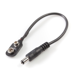
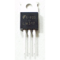
Input power can be supplied to either the DC barrel jack or the two pin header labeled + and -. Output power is supplied to the pins labeled GND and VCC. Board has both an On/Off switch and a voltage select switch (3.3V/5V).
The two sets of four GND and VCC holes are spaced such that when connected to our Basic Breadboard both power busses will be powered.
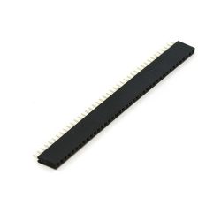
Note: Headers are not supplied. You will need to supply your own headers to connect this board to a breadboard. Check below for some breakaway header strips.
Dimensions: 2.15x0.65"
Features:
- 6-12V input voltage via barrel jack or 2-pin header
- 3.3V or 5V regulated output voltage
- 800mA Operating Current
- ON/OFF switch
- Output voltage select switch
- Power status LED
- PTC fuse protected power
- 5.5x2.1mm center positive barrel jack
Documents:
- [Schematic](https://cdn.sparkfun.com/datasheets/Prototyping/Breadboard Power Supply - 5-3.3SMD_V14.pdf)
- [Eagle Files](https://cdn.sparkfun.com/datasheets/Prototyping/Breadboard Power Supply - 5-3.3SMD_V14.zip)
- Unregulated Power Supply Tutorial
- GitHub (Design Files)


Features & Specs
- 6-12V input voltage via barrel jack or 2-pin header
- 3.3V or 5V regulated output voltage
- 800mA Operating Current
- ON/OFF switch
- Output voltage select switch
- Power status LED
- PTC fuse protected power
- 5.5x2.1mm center positive barrel jack
- 2.15x0.65"
Documentation
- Schematic
- Eagle Files
- Unregulated Power Supply Tutorial
- GitHub (Design Files)
Customer Reviews

Stock and Customer Discounts
Available Discounts
- $9.45 | 10+ units
- $8.96 | 25+ units
- $8.46 | 100+ units