Fingerprint Scanner - 5V TTL

Replacement:SEN-11792. The updated version of the GT-511 has an increased memory capacity and 360° recognition. This page is for reference only.

Fingerprint scanners are awesome. Why use a key when you have one right at the tip of your finger? Unfortunately, they're usually unreliable or difficult to implement. Well not anymore! We've found this great fingerprint module from ADH-Tech that communicates over TTL Serial so you can easily embed it into your next project.

The module itself does all of the heavy lifting behind reading and identifying the fingerprints with an on-board optical sensor and 32-bit CPU. All you need to do is send it simple commands. To get started, just register each fingerprint that you want to store by sending the corresponding command and pressing your finger against the reader three times. The fingerprint scanner can store up to 20 different fingerprints and the database of prints can even be downloaded from the unit and distributed to other modules. As well as the fingerprint "template," the analyzed version of the print, you can also retrieve the image of a fingerprint and even pull raw images from the optical sensor!

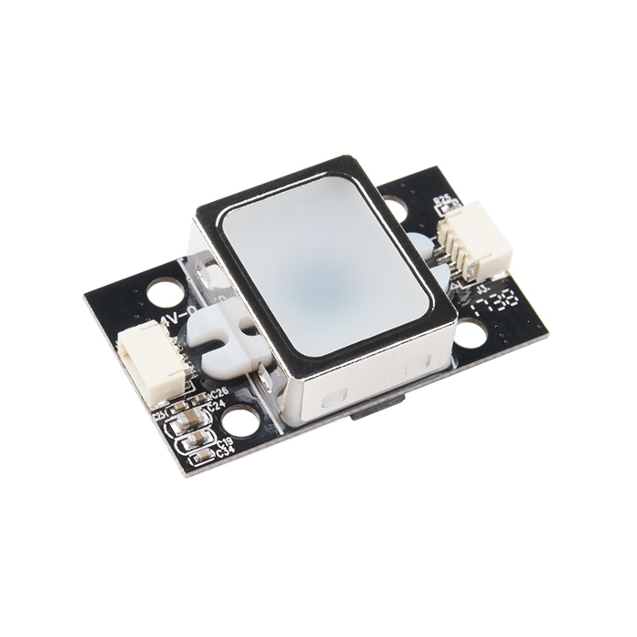
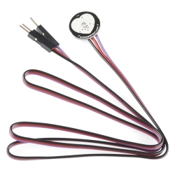
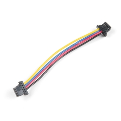
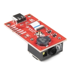
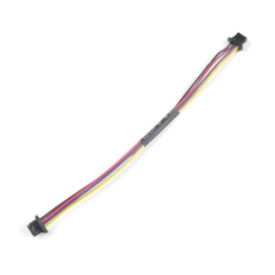
The module is small and easy to mount using two mounting tabs on the side of the sensor. The on-board JST-SH connector has four signals: Vcc, GND, Tx, Rx. A compatible JST-SH pigtail can be found in the related items below. Demo software for PC is available in the documents below, simply connect the module to your computer using an FTDI Breakout and start the software to read fingerprints!

  • High-Speed, High-Accuracy Fingerprint Identification using the SmackFinger 3.0 Algorithm
  • Download Fingerprint Images from the Device
  • Read and Write Fingerprint Templates and Databases
  • Simple UART protocol (Default 115200 baud)
  • Capable of 1:1 Verification and 1:N Identification

  • 37 x 17 x 9.5 mm

Fingerprint Scanner - 5V TTL Product Help and Resources

Comments

Looking for answers to technical questions?

We welcome your comments and suggestions below. However, if you are looking for solutions to technical questions please see our Technical Assistance page.

  • Sapporo / about 11 years ago / 2

    USB PINOUTS: I just got this device to work on DIRECT USB. The ( unpopulated) J1 connector is the USB interface , and auto-installs as a CDROM device in windows. I just used an old USB AB cable , snipping off the 'B' end, and exposing wires ( red, white, green, black.) They attach in that order starting from pin 1 (square pad). The SDK_DEMO.exe software worked well (selecting 'USB') in win7 on my 64-bit machine, but not my 32bit XP desktop. Im trying to port the 'protocol.c' to my RPi

  • Member #407943 / about 11 years ago / 2

    Is the JST SH Jumper 4 Wire Assembly - 8" PRT-10359 the right connector for this module?

  • tiagofumo / about 11 years ago / 2

    that product is awesome, it's the perfect example of products sparkfun should have... simple to use, full of features, accessible price compared to other options, etc

  • diametric / about 11 years ago / 2

    Does anyone know if this is susceptible to the sausage attack, or similar methods? Essentially a properly warmed raw breakfast sausage link (if the scanner looks for body temperatures) placed over a scanner that already has a latent print on it will usually be recognized as the print. If this is just using a camera like described, it seems like it would be. Maybe someone at SparkFun can test it?

    • Madone / about 11 years ago * / 3

      Just keep typical transparent tape near by. Press the tape to the scanner and remove. It does a fantastic job cleaning finger print sensors like this. If you are extra paranoid then dispose of the tape in a destructive manner because it does a great job lifting the print from the surface.

      If you are worried about security then you should be worried that the response from the sensor for a 1:1 and 1:N verification is not encrypted and the verification takes place at the sensor. So, a would be hacker could just remove the sensor and send some basic serial commands to spoof the system.

    • Far_Seeker / about 11 years ago * / 2

      Hmm even if it was, I'd imagine it would be a fairly easy to prevent unauthorized access by using a microfiber cloth or disposable lens wipe to wipe the sensor area after you scan your finger. Remember cleanliness is next to paranoia!

  • Member #425668 / about 11 years ago / 1

    each time i try to enroll it. it will say device error?what is the problem actually?plzz help

    • Member #427260 / about 11 years ago * / 1

      MIke , each time i try to enroll it says device error can any body tell me the reason and the solution if their is a one

      • I would recommend checking out our support page here and email techsupport@sparkfun.com. They should be able to help you out.

  • Member #425668 / about 11 years ago / 1

    i bought this device.to connect to the laptop does it need i usb to serial convertor. can i use UC00A convertor?plzzz help me

  • Member #424639 / about 11 years ago / 1

    Guys in the Command packet what will be the size of it? the first thing to send is 0x55,0xaa,deviceID,input,command,sum....so will the size be 6?, or 10, or more...& if it is 10 or more what will be the redundant bytes/words/Dwords added..will it just be the repetition or zeros or what?

    Thank you

  • Member #341499 / about 11 years ago / 1

    Any idea when this will be back in stock?

  • Member #424639 / about 11 years ago / 1

    Guys where is the Vcc, ground , tx & Rx

    • MikeGrusin / about 11 years ago / 1

      In the datasheet, in the mechanical drawing on the last page. Pin 1 is marked by a white triangle on the PCB.

      • Member #424639 / about 11 years ago / 1

        Mike, In the Command packet what will be the size of it? the first thing to send is 0x55,0xaa,deviceID,input,command,sum….so will the size be 6?, or 10, or more…& if it is 10 or more what will be the redundant bytes/words/Dwords added..will it just be the repetition or zeros or what? Thank you so much for replying

        • MikeGrusin / about 11 years ago / 1

          I haven't personally used this fingerprint reader, but this information should all be in the datasheet. Page 6 describes the command packet, which must be 10 bytes. A word is two bytes, a dword four bytes. If your numbers aren't big enough to fill the upper bytes, you'll still have to send the extra bytes as zeroes (or two's-complement if the data is signed). You might try asking in our forums as well. Good luck!

  • KairaMonni / about 11 years ago / 1

    Worked well while it worked . I connected the reader by usb and run the demo software . I enrolled a few fingers and it worked surprisingly well , after a while of fiddling with the unit i closed the usb connection and unplugged the unit . I thought of many places where i could put a fingerprint reader , i decided to install this one in my car . Today i tried the demo software again , when i open the connection it displays serial and firmware versions , displays enroll count , deletes fingerprints , but does not enroll or read fingerprints any more . When i click enroll the blue led flashes briefly in the reader and the software displays Device error! , if i click verify the blue led comes on but does not recognize a finger and after awhile displays time out ... I may buy another but it would be nice to know why this one died ... Maybe the writer of the demo software has not read the special note ?

  • fanyca / about 11 years ago / 1

    Hi guys, Im trying to capture of fingerprint image with the command CaptureFinger but this command return me a Non-ack exctaly the nack parameter that mean NACK_DEV_ERR Value: 0x100F, in th description of the parameter say: "Device Error, especially if Crypto-Chip is trouble".

    What I can do? What means this? Help somebody!!!

    • Member #427260 / about 11 years ago / 1

      i have the same problem would any one tell me why it happened and is their any solution to these problem or the finger print is dead and i have to buy another one

  • fanyca / about 11 years ago / 1

    Hey, I found this code about this sensor... I'll put it here as aid:

    //--------------------------------------------------------------------------------------------

    //Fingerprint Scanner TTL demo code to show how to cmdOpen and show device id and serial number // Note: all multi byte data is little endian!

    include

    SoftwareSerial Scanner(11, 12); // RX as pin 11

    int f; byte ResponseData[38];

    void setup() { Scanner.begin(9600); Serial.begin(9600); }

    void loop() { // cmdOpen with response data packet Scanner.write((byte)0x55); Scanner.write((byte)0xAA); Scanner.write((byte)0x01); Scanner.write((byte)0x00); Scanner.write((byte)0x01); Scanner.write((byte)0x00); Scanner.write((byte)0x00); Scanner.write((byte)0x00); Scanner.write((byte)0x01); Scanner.write((byte)0x00); Scanner.write((byte)0x02); // pre-calculated checksum Scanner.write((byte)0x01); delay(100);

    if (Scanner.available() > 0 ) {

    for (f = 0; f < 38; f++) { ResponseData[f] = Scanner.read(),HEX; } }

    Serial.print("FirmwareVersion: "); for (f = 16; f < 20; f++) { Serial.print(ResponseData[f],HEX); //FirmwareVersion } Serial.println(); Serial.print("DeviceSerialNumber: "); for (f = 20; f < 36; f++) { Serial.print(ResponseData[f],HEX); //SerialNumber }

    while(1){}

    }

    //---------------------------------------------------------------------------------------------

  • Member #418982 / about 11 years ago / 1

    To make this scanner talk to the program I need a PRT 10359 and then a FTDI break out board right? any recommendations on a breakout board? 5volt DEV-09716 would be a good one?

  • Member #418773 / about 11 years ago / 1

    What can you tell me about waterproof of the scanner part?

  • fanyca / about 11 years ago / 1

    In this Video http://www.youtube.com/watch?feature=player_embedded&v=s0WRSgCJLIg ... What color in the cable is Rx and What is Tx? - at 1:04 min (Green or White)

  • fanyca / about 11 years ago / 1

    Anyone has the datasheet of this sensor? I need make physical adjust because I don't have the cable and I can't waiting 2 weeks for that ( I'm not live in USA).

  • fanyca / about 11 years ago / 1

    Hi! I bougth one this, but it didn't come with a cable to connect it. Where can i find one of those? I saw that I can buy it in this page (https://www.sparkfun.com/products/10359?) too but I wanna test my module immediately.

    Anyone know any way to make an adapter that looks like the cable or get cable without having to buy it. ?

  • ddegn / about 11 years ago / 1

    Has anyone got the software to work with Windows7? It seems to want to use the "My Documents" folder from older Windows versions. I noticed the possible comm ports only go up to 10. If you've used a bunch of different FTDI devices with your PC (as I have), you may have some trouble.

  • Member #49495 / about 11 years ago / 1

    Hello,

    Does this module support an extra layer (~ 2mm) of transparent glass or acrylic?

    I'd like to make a case for it without the hole, so it would be used behind the case wall.

    Thank you

    • thefug / about 11 years ago * / 1

      I guess not ? because you also have to press a little to activate the build-in switch, and this starts the "scan" ? (btw. your "greasy" vinger has to make contact with the "window" for the good working of it all)

  • thefug / about 11 years ago / 1

    And Sparkfun's PRT-10359 is the correct jumper-connector-wire-leads assy ?

    • CraigTheCoder / about 11 years ago / 1

      Yes, PRT-10359 is the correct cable. I am not entirely certain why Sparkfun included 2 different 4-wire JST connector cables in their "Selected by our staff" related items section, but it does cause some confusion. I forgot to originally order the cable with my fingerprint scanners and ended up having to order (separately) both kinds to ensure at least one would be the correct form factor. So, PRT-09916 (rainbow wires) is NOT the correct connection lead....PRT-10359 (black and white wires) IS the one you want for this application.

      • thefug / about 11 years ago / 1

        Also...... by looking at the pictures, the "onboard" JST connector, is a SMD version, so, not a through-hole version..... and on the other side of the pcb i see "J1" contacts, are these the same as the JST ? if so, one could make a break-out board, or put it on a prototype shield, the "ears" will help too, to have it mount steady.

        • ddegn / about 11 years ago / 1

          "J1" just numbers the connections; it doesn't indicate the type of connector. I'm not sure if "J" stands for "jumper" or what but it's common to see connections with a J# silkscreen. I found a connector that fit in my bag of old connectors harvested from old electronics.

          • sorphin / about 11 years ago / 1

            "thefug" wasn't asking if J1 was a JST connector, they were asking if the J1 pads connect to the same points as the JST connector does, thereby avoiding having to use the JST connection... My module just arrived. I'll tone it out and post my result later.

            • ddegn / about 11 years ago / 1

              Ah, yes. That makes more sense. The J1 pads do not correspond to pins in the JST connection. The two pads farthest away from the "J1" silkscreen are both ground but the other three pads are not connected to any of the other JST pins.

              • sorphin / about 11 years ago / 1

                Yeah, I confirmed that a little bit ago.. tis a shame, since that would be so much easier than this stupid jst cable i now have to buy (because I missed that I needed it, since they don't include cables ever).. I'm having to figure out more stuff to buy to justify the shipping for a $1.50 cable.

    • ddegn / about 11 years ago / 1

      That looks like the right connector. The four pins are 1mm apart. (I didn't think to order a connector when I ordered a scanner.)

  • patrick_m / about 11 years ago / 1

    Would there any way to have more than 20 users, say by storing them on a microsd or even a computer?

    • Quazar / about 11 years ago / 1

      It can't store more than 20 users at a time, but because you can upload and download templates, you can store the templates yourself and just upload them as needed. You could have the device scan the current user and then send you the template. You could then upload groups of 20 users and have the device compare to see if there is a match in that group. Repeat as needed.

      I suspect this would be quite slow, though.

      If you can figure out how to compare the templates yourself, you could just maintain the database of user templates elsewhere (e.g., in an Arduino) and do the matching yourself.

      • Patchido / about 11 years ago / 1

        This is exactly what im aiming for, has anyone tried this? How slow is it? whats the highest speed the device can handle?

  • LloydA / about 11 years ago / 1

    In the datasheet it mentioned using ISO CD images. What???

  • Tadpole / about 11 years ago / 1

    I'm almost ashamed to ask but, are you going to offer a simple arduino example for this device?

    • Jon Mayer / about 11 years ago / 1

      It really shouldn't be too hard. Serial communication is pretty standard on Arduino, just have to send the right commands.

      • sorphin / about 11 years ago / 1

        You'd think that... I'm working on a library for it.. and looking at 'some fruit''s code for ideas.. sending the packet structure is a pain in the behind.

        • fanyca / about 11 years ago / 1

          -.-'' yes it's so dificult... I try to communicate with the sensor even i can't. I don't understand why? I'm using an arduino mega 2560 for serial communication and I saw and compare the adafruit library and... nothing. Any idea?

Customer Reviews

No reviews yet.