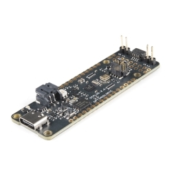
SparkFun 9DoF IMU Breakout - ICM-20948 (Qwiic)
The SparkFun 9DoF IMU Breakout incorporates all the amazing features of the ICM-20948 into a Qwiic-enabled breakout board.
Helpful Documentation
 Hookup Guide
 Datasheet (ICM-20948)
 Schematic
Product Overview
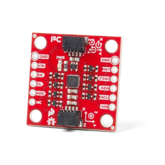
The SparkFun 9DoF IMU Breakout incorporates all the amazing features of Invensense's ICM-20948 into a Qwiic-enabled breakout board complete with a logic shifter and broken out GPIO pins for all your motion sensing needs. The ICM-20948 itself is an extremely low powered, I2C and SPI enabled 9-axis motion tracking device that is ideally suited for smartphones, tablets, wearable sensors, and IoT applications. Utilizing our handy Qwiic system, no soldering is required to connect it to the rest of your system. However, we still have broken out 0.1"-spaced pins in case you prefer to use a breadboard.
In addition to the 3-Axis Gyroscope with four selectable ranges, 3-Axis Accelerometer, again with four selectable ranges, and 3-axis magnetometer with an FSR to ±4900µT, the ICM-20948 also includes a Digital Motion Processor that offloads the computation of motion sensing algorithms from the detectors, allowing optimal performance of the sensors. We've also broken out all the ICM-20948 pin functionality to GPIO and labeled them I2C on the front, SPI on the back for ease of identification.
Note: The I2C address of the ICM-20948 is 0x69 and is jumper selectable to 0x68. A multiplexer/Mux is required to communicate to multiple ICM-20948 sensors on a single bus. If you need to use more than one ICM-20948 sensor consider using the Qwiic Mux Breakout.
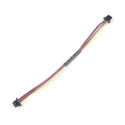
The SparkFun Qwiic Connect System is an ecosystem of I2C sensors, actuators, shields and cables that make prototyping faster and less prone to error. All Qwiic-enabled boards use a common 1mm pitch, 4-pin JST connector. This reduces the amount of required PCB space, and polarized connections mean you can’t hook it up wrong.


Features & Specs
- 1.95 V to 3.6 V supply voltage
- Triple-axis MEMS gyroscope with user-programmable full-scale range of ±250 dps, ±500 dps, ±1000 dps, and ±2000 dps
- Triple-axis MEMS accelerometer with programmable full scale range of ±2g, ±4g, ±8g, and ±16g
- Triple-axis silicon monolithic Hall-effect magnetic sensor with full scale measurement range to ±4900 µT
- I2C at up to 100 kHz (standard-mode) or up to 400 kHz (fast-mode) or SPI at up to 7 MHz for communication with registers
- On-board digital motion processor (DMP)
- Digital-output temperature sensor
- 2x Qwiic Connection Ports
- I2C Address: 0x69 (0x68 with Jumper)
Documentation
Customer Reviews

Stock and Customer Discounts
Available Discounts
- $20.85 | 10+ units
- $19.76 | 25+ units
- $18.66 | 100+ units