SparkFun 16x2 SerLCD - RGB Text (Qwiic)
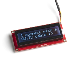
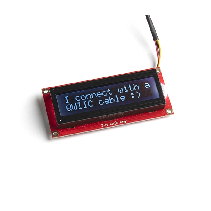
The SparkFun Qwiic SerLCD is a serial enabled LCD that provides a simple and cost effective solution for adding a 16x2 RGB on Black LCD to a project.
Helpful Documentation
 Hookup Guide
Product Overview
The SparkFun SerLCD is an AVR-based, serial enabled LCD that provides a simple and cost effective solution for adding a 16x2 RGB on Black Liquid Crystal Display into your project. We've seriously overhauled the PCB design on the back of the screen by including an ATmega328P that handles all of the screen control, meaning a backpack is no longer needed! This display can now communicate in three different ways: serial, I2C, and SPI. This comes equipped with a Qwiic connector, bringing serial LCDs into the Qwiic ecosystem. This simplifies the number of wires needed and allows your project to display all kinds of text and numbers.
The on-board ATmega328P AVR microcontroller utilizes 11.0592 MHz crystal for greater communication accuracy with adjustable baud rates of 1200 through 1000000 but is default set at 9600. The firmware for this SerLCD is fully opensource and allows for any customizations you may need.
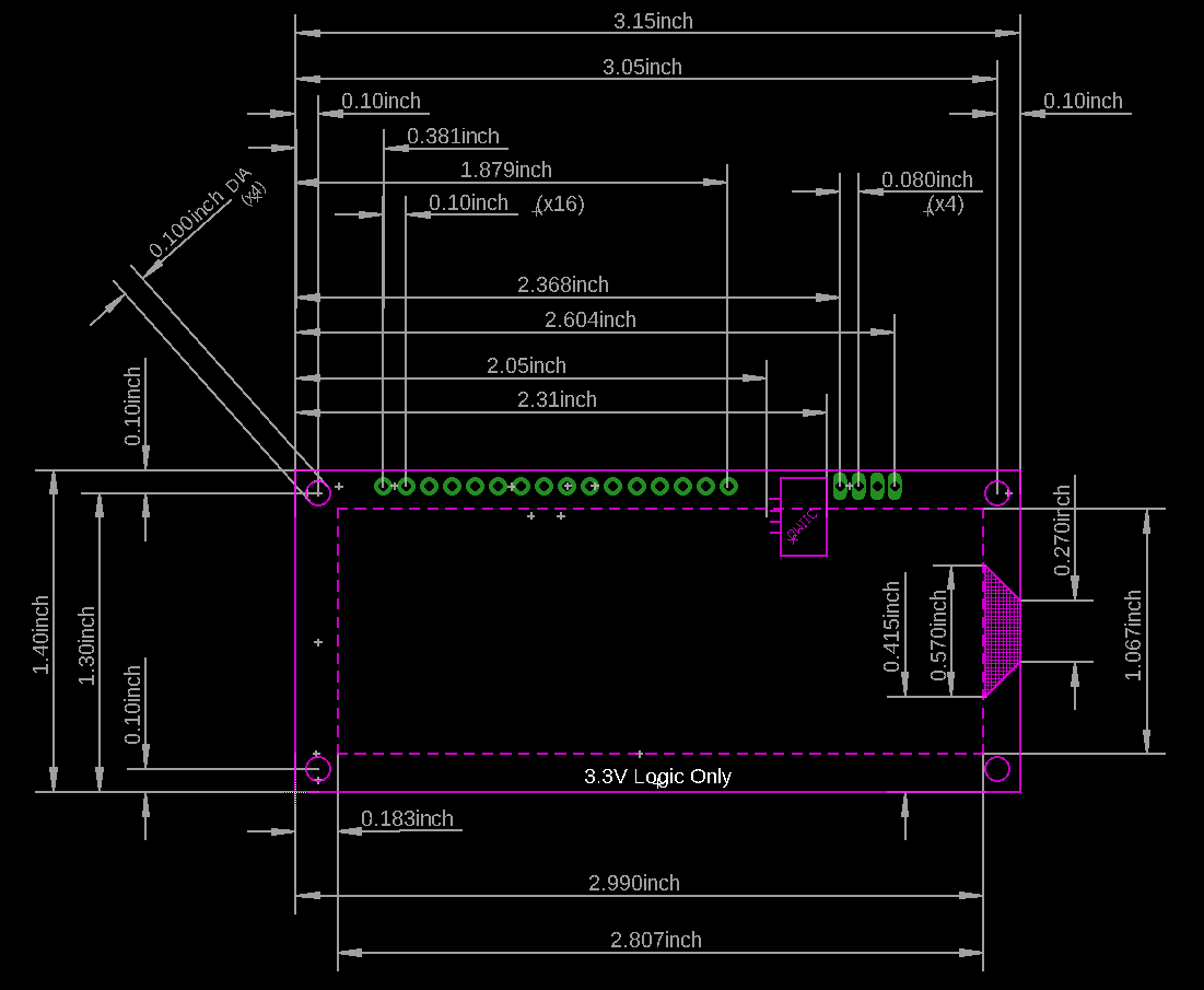
Note: Since the SerLCD is a 3.3V device, please make sure you convert to 3.3V logic depending on your chosen microcontroller or single board computer. Otherwise, you may risk damaging your board.


Features & Specs
- 16x2, RGB on Black Display
- The AVR ATMega328p (with Arduino-compatible bootloader) is populated on the back of each LCD screen and handles all of the LCD control
- Three communication options: Serial, I2C and SPI
- Adjustable I2C address controlled via software special commands (0x72 default)
- Qwiic connection
- Emergency reset to factory settings (Jumper RX to GND on bootup)
- Operational backspace character
- Incoming buffer stores up to 80 characters
- Pulse width modulation of backlight allows direct control of backlight brightness and current consumption
- Pulse width modulation of contrast allows for software defined contrast amount.
- User definable splash screen
- Open-sourced firmware and Arduino-compatible bootloader enables updates via the Arduino IDE
- Dimensions (LxWxH): 80.02x36.13x14.27mm
- Weight: 0.0779 oz.
Customer Reviews