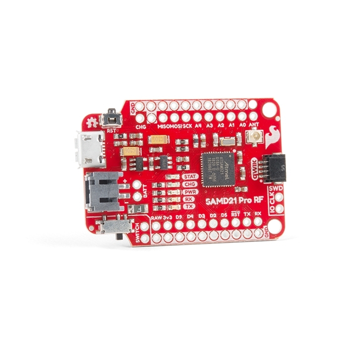
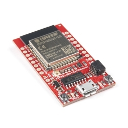
SparkFun Pro RF - LoRa, 915MHz (SAMD21)
The SparkFun Pro RF is a LoRa®-enabled wireless board that marries a SAMD21 and a long-range RFM95W to make a compact and easy-to-use IoT Arduino board.
Helpful Documentation
 Hookup Guide
 Schematic
 Datasheet SAMD21G
Product Overview
The SparkFun Pro RF is a LoRa®-enabled wireless board that marries a SAMD21 and a long-range RFM95W to make a compact and easy-to-use IoT Arduino board. With its fast MCU and excellent point to point data transmission in the 915MHz ISM band with LoRa Capabilities, the Pro RF is a great choice for anyone interested or experienced in utilizing long range data communication.
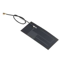
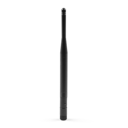
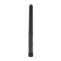
Every pin on the SparkFun Pro RF is accompanied with a ground connection making the buttons and LEDs easy to connect. In case you're building something to be embedded into clothing or other physically harsh environment the antenna includes a stress relief hole to make sure your wire antenna survives. A short (3 inch) wire antenna is sufficient for "short" distances (up to 1 mile line-of-sight), but we've also included a u.FL antennae connector for potentially longer distances.
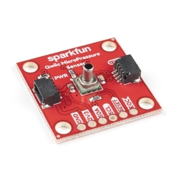
The Pro RF also includes a power switch and 2-pin JST connector for powering from a lithium battery. With a Micro-B USB and the power switch in the off position, the Pro RF will charge the attached battery! The board programs over a reinforced Micro-B connector with a slim reset button that fits nicely on the side of the board. We’ve even added our popular Qwiic connector to the edge of the board making it incredibly easy to add sensors and actuators without the need for solder or a soldering iron!
Thanks to the Arduino LoRa library, the RFM95W radio is an easy to use packet radio. But it doesn’t stop there because closing a few jumpers on the underside of the SAMD21 Pro RF initiates LoRaWAN mode on the radio module making it a node in a distributed sensor network.
-
-
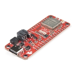
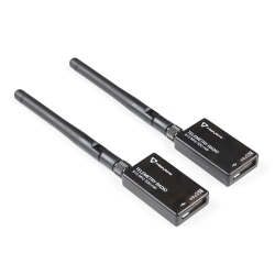
 SparkFun IoT Node for LoRaWAN®
Special Price Current price: $49.95 Regular Price Original price: $99.95In stock
SparkFun IoT Node for LoRaWAN®
Special Price Current price: $49.95 Regular Price Original price: $99.95In stock -
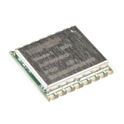
 LoRa/FSK Transceiver Module - 915MHz (RFM97CW)
Special Price Current price: $5.99 Regular Price Original price: $9.95Discontinued
LoRa/FSK Transceiver Module - 915MHz (RFM97CW)
Special Price Current price: $5.99 Regular Price Original price: $9.95Discontinued -
-
-
-
-
-
-
-
-
-


Features & Specs
- SAMD21G18A
- Cortex M0+
- 256KB Flash Memory
- 32MHz External Oscillator
- 4 Digital and 5 Analog IO Pins with exclusive GND pins
- Hope RFM95W LoRa modem
- Point to Point Radio capabilities
- LoRa Enabled
- Frequency range: 915 MHz
- Spread factor: 6-12
- Range up to 1 mile line of sight
- U.FL Antenna
- LiPo Battery Charger
- 500mA Charge Rate
- Qwiic Enabled
- Power LED disconnect jumper for low power applications.
- PTH pins for software debug (SWD)
Revision Changes: On this revision of the SAMD21 Pro RF, we have made a few changes to improve the board, listed below. If users are unsure about which version they purchased, please refer to the product pictures.
- Fixed the VDDCORE pin connection issue
- Broken out an LED jumper for low power applications
- Added PTH pins for software debug (SWD)
Documentation
Customer Reviews

Stock and Customer Discounts
Available Discounts
- $35.10 | 10+ units
- $33.26 | 25+ units
- $31.41 | 100+ units