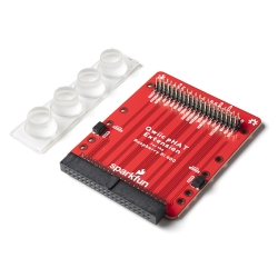
SparkFun VR IMU Breakout - BNO086 (Qwiic)
The SparkFun VR IMU Breakout is a cutting-edge triple-axis accelerometer/gyro/magnetometer in a single package that you can connect via I2C and Qwiic!
Helpful Documentation
 Hookup Guide
 Schematic
 Datasheet (BNO086)
Product Overview
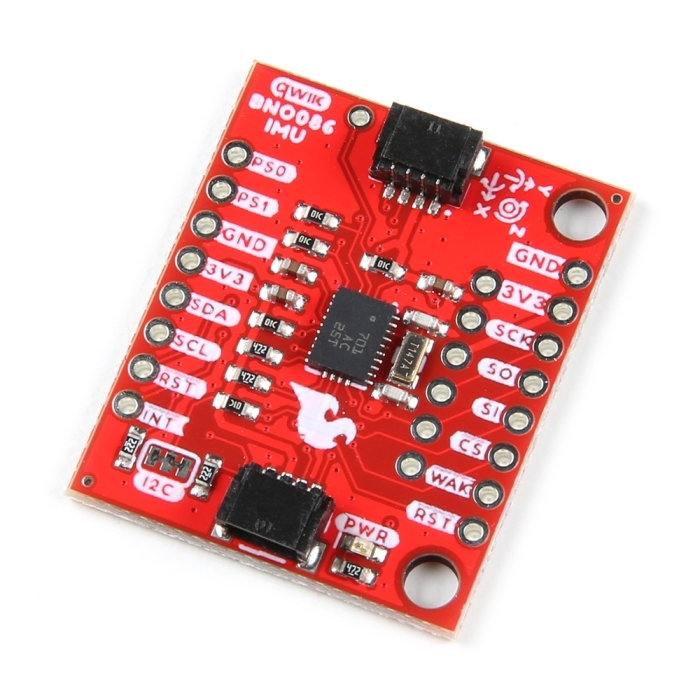
Virtual reality is in, but you shouldn't have to drop hundreds of dollars to gain access to the technology behind it. Luckily, that's where the SparkFun VR IMU Breakout comes in. At its heart is CEVA’s BNO086, a combination triple-axis accelerometer/gyro/magnetometer System in Package (SiP) with a 32-bit ARM© Cortex™ M0+. The BNO086 Inertial Measurement Unit (IMU) produces accurate rotation vector headings, excellently suited for VR and other heading applications, with a two-degree or less static rotation error. The VR IMU is exactly what we’ve been waiting for; all the sensor data is combined and drift-corrected into meaningful, accurate IMU information. It’s perfect for any project that needs to sense orientation or motion.
This IMU breakout board has also been equipped with two I2C Qwiic connectors to make interfacing with the tiny QFN package a bit easier. It’s part of SparkFun’s Qwiic connect system, so you won’t have to do any soldering to figure out how things are oriented. However, we still have broken out 0.1"-spaced pins if you prefer to use a breadboard.
The BNO080 was designed to be implemented in Android-based cellular phones to handle all the computations necessary for virtual reality goggles using only your phone. With the BNO080 EOL, CEVA offers the drop-in replacement BNO086 with enhanced features (14-bit accelerometer fusion, reduced idle state power, and Interactive Calibration). The sensor is quite powerful, and with power comes a complex interface. Thanks to the solder jumpers on the board, you can select between two different I2C addresses. Still, if I2C is not your first communication choice, the sensor can communicate over SPI and UART! We’ve also written an I2C-based library that provides the rotation vector (the reading most folks want from an IMU), acceleration, gyro and magnetometer readings, step counting, and activity classifier (such as riding a bike).


Features & Specs
- Operating Voltage
- 2.4V - 3.6V
- Typically 3.3V via Qwiic cable
- I2C (Default): Up to 400kHz
- SPI: Up to 3MHz
- UART: 3Mbps
- Rotation Vector
- Dynamic Error: 3.5°
- Static Error: 2.0°
- Gaming Rotation Vector
- Dynamic Error: 2.5°
- Static Error: 1.5°
- Dynamic Heading Drift: 0.5° / min
- Geomagnetic Rotation Vector
- Dynamic Rotation Error: 4.5°
- Static Rotation Error: 3.0°
- Gravity Angle Error: 1.5°
- Linear Acceleration Accuracy: 0.35m/s2
- Accelerometer Accuracy: 0.3m/s2
- Gyroscope Accuracy: 3.1° / sec
- Magnetometer Accuracy: 1.4µT
- 2x Qwiic Connection Ports
- I2C Address: 0x4B (default), 0x4A
- I2C Pull-Up Resistors (2.2kΩ)
- Power LED
- Jumpers
- Power LED
- I2C Pull-up Resistors
- Address Select
- Protocol Selection 0
- Protocol Selection 1
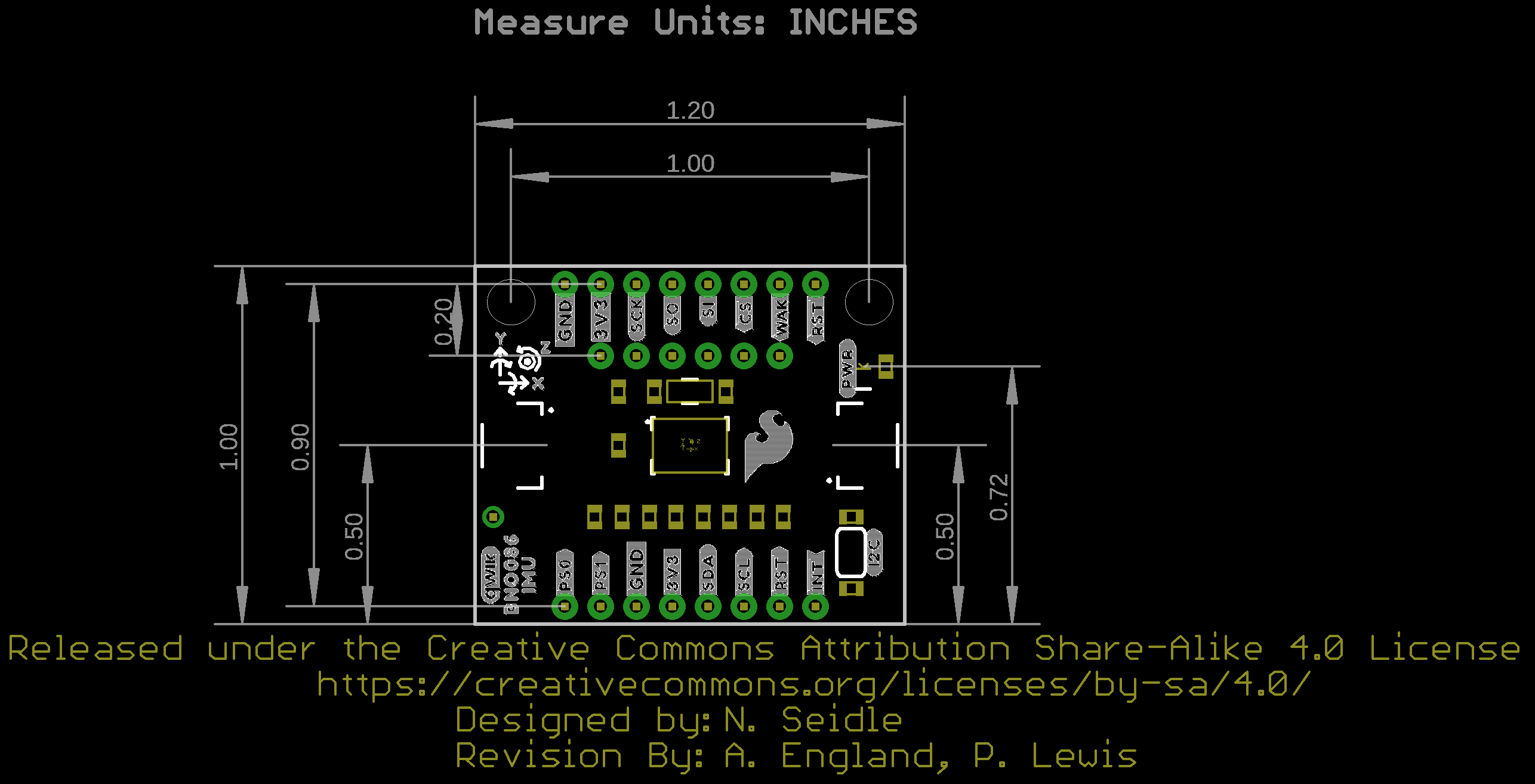
- Board Dimensions: 1.0in. x 1.2in. (25.4mm x 30.48mm)
- Weight: 3g
Customer Reviews

Stock and Customer Discounts
Available Discounts
- $33.20 | 10+ units
- $31.46 | 25+ units
- $29.71 | 100+ units