- Home
- Product Categories
- Infrared
- SparkFun IR Array Breakout - 110 Degree FOV, MLX90640 (Qwiic)

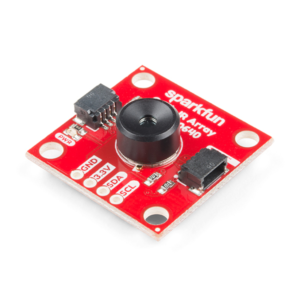
SparkFun IR Array Breakout - 110 Degree FOV, MLX90640 (Qwiic)
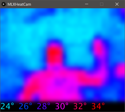
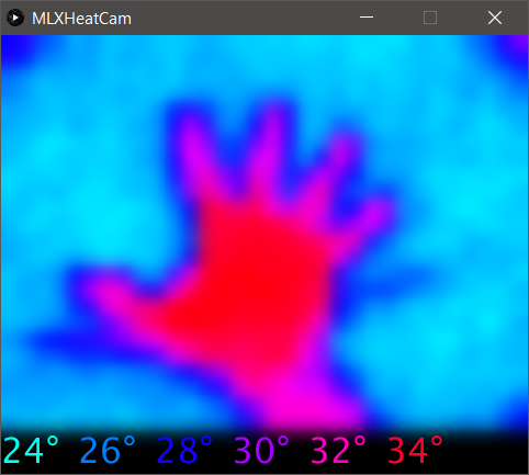
It's time to say hip hip array for this IR Breakout! The MLX90640 SparkFun IR Array Breakout is equipped with a 32x24 array of thermopile sensors creating, in essence, a low resolution thermal imaging camera. With this breakout you can detect surface temperatures from many feet away with an accuracy of ±1.5°C (best case). To make it even easier to get your low-resolution infrared image, all communication is enacted exclusively via I2C, utilizing our handy Qwiic system. However, we still have broken out 0.1"-spaced pins in case you prefer to use a breadboard.
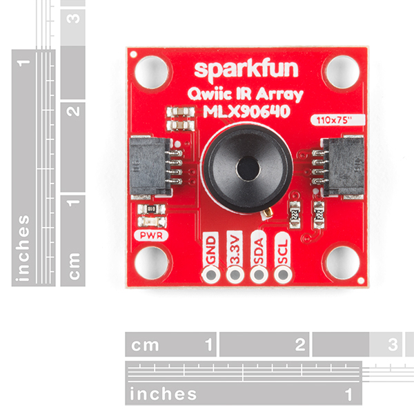
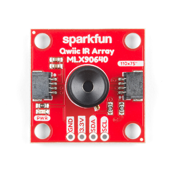
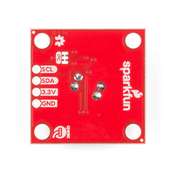
This specific IR Array Breakout features a 110°x75° field of view with a temperature measurement range of -40°C-300°C. The MLX90640 IR Array has pull up resistors attached to the I2C bus; both can be removed by cutting the traces on the corresponding jumpers on the back of the board. Please be aware that the MLX90640 requires complex calculations by the host platform so a regular Arduino Uno (or equivalent) doesn't have enough RAM or flash to complete the complex computations required to turn the raw pixel data into temperature data. You will need a microcontroller with 20,000 bytes or more of RAM. To achieve this, we recommend a Teensy 3.1 or above.
Note: The I2C address of the MLX90640 is 0x33 and is hardware defined. A multiplexer/Mux is required to communicate to multiple MLX90640 sensors on a single bus. If you need to use more than one MLX90640 sensor consider using the Qwiic Mux Breakout.
The SparkFun Qwiic connect system is an ecosystem of I2C sensors, actuators, shields and cables that make prototyping faster and less prone to error. All Qwiic-enabled boards use a common 1mm pitch, 4-pin JST connector. This reduces the amount of required PCB space, and polarized connections mean you can’t hook it up wrong.
- Operating Voltage: 3V-3.6V
- Current Consumption: ~18mA
- Field of View: 110°x75°
- Measurement Range: -40°C-300°C
- Resolution: ±1.5°C
- Refresh Rate: 0.5Hz-64Hz
- I2C Address: 0x33
- 2x Qwiic Connection Ports
- Schematic
- Eagle Files
- Hookup Guide
- Datasheet (MLX90640)
- GitHub
SparkFun IR Array Breakout - 110 Degree FOV, MLX90640 (Qwiic) Product Help and Resources
Qwiic IR Array (MLX90640) Hookup Guide
September 20, 2018
The Melexis MLX90640 contains a 32x24 array of thermopile sensors creating, in essence, a low resolution thermal imaging camera. In this guide, we’ll go over how to connect your Qwiic Infrared Array with MLX90640 and get it communicating with Processing to produce a nice thermal image.
Core Skill: Programming
If a board needs code or communicates somehow, you're going to need to know how to program or interface with it. The programming skill is all about communication and code.
Skill Level: Competent - The toolchain for programming is a bit more complex and will examples may not be explicitly provided for you. You will be required to have a fundamental knowledge of programming and be required to provide your own code. You may need to modify existing libraries or code to work with your specific hardware. Sensor and hardware interfaces will be SPI or I2C.
See all skill levels
Core Skill: Electrical Prototyping
If it requires power, you need to know how much, what all the pins do, and how to hook it up. You may need to reference datasheets, schematics, and know the ins and outs of electronics.
Skill Level: Competent - You will be required to reference a datasheet or schematic to know how to use a component. Your knowledge of a datasheet will only require basic features like power requirements, pinouts, or communications type. Also, you may need a power supply that?s greater than 12V or more than 1A worth of current.
See all skill levels
Comments
Looking for answers to technical questions?
We welcome your comments and suggestions below. However, if you are looking for solutions to technical questions please see our Technical Assistance page.
Customer Reviews
3 out of 5
Based on 6 ratings:
1 of 1 found this helpful:
Works great for me!
Have purchased many of these and all work flawlessly!
Nice idea, bad implementation
I bought 87 units. Yes, that's a lot of units. About 15% were faulty. We touched up all the faulty ones with soldering iron to reflow solder. about 5% came back to life. Rest of the units are dead, or so it appears. Based on Sparkfun tech support, there is a known issue with these: "thermal issue where minor temperature changes cause the case to expand and begin shorting out on the PCB".
The customer support is horrible thought. More than a month later, I don't have replacement working units or my money back. Stay away.
Sensor and code support is great, PCB could be improved
When this works, it works well. You do need a decent micro to run it with the provided code examples. However, mine worked one day and quit the next. After some reading it seems the I2C signals (SDA) can short to ground due to some marginal PCB design. The bottom metal of the part is ground, which makes it easier to short traces/copper to it accidentally. The board could be improved in a few ways- use a custom insulator/thermal pad under the part, leave a copper void under the part,or both. At least use vias to avoid running traces (SDA) under the metal bottom area of the part.
imaging sensor is misaligned
The sensor is skewed diagonally so that the image is rotated when the board is mounted normally. This is a design defect, looking at the spec sheet one could determine this based on the location of the metal tab on the lens. The sensor needs to be rotated ~15 degrees so that it actually aligns with the edge of the PCB.
Pretty cool
Works well, setup guide and code is very informative and helpful
I am curious about the stated low end of the IR detection range of -40°C. How cold must the array be to achieve this?
Is it possible to change the lens on this device ? How is it attached ?
Hi there, it sounds like you are looking for technical assistance. Please use the link in the banner above, to get started with posting a topic in our forums. Our technical support team will do their best to assist you.
That being said, I am pretty sure it is not possible to remove the lens as there is no information in the datasheet regarding that. Please, DO NOT try to do so, you will most likely end up damaging your device. You may need to contact the sensor manufacturer (listed on the datasheet) if there is a way to remove the lens; unfortunately, we don't have that information.
Hi, can this work with Raspberry pi 3?
Hi, I recently bought this sensor. I am using an Arduino Due and the source code provided for "Basic Readings", but there seems to be an issue during the parsing of EEPROM information. The function MLX90640_ExtractParameters() returns -4. I traced this error code to the function ExtractDeviatingPixels(): which returns a -4 because of the following statement:
else if(outlierPixCnt > 4)
This seems to cause all of the values to be NaN (I'm assuming there is a divide by zero somewhere). Any suggestions?
I look at the I2C buss traffic with a logic analyzer, and notice that Arduino is requesting data in 32 byte chunks (starting at 0x2400). However, every 32 bytes of received data are identical to the first 32-bytes...something is not right
Note that as with the black board, the orientation of the device, and hence the "image", is not square with any edge of the board. See tab.
The temperature measurement range is incorrect. -40 to 85°C is the operational temperature range. The sensor can measure object temperature between -40 to 300°C.