- Home
- Product Categories
- FPGA
- Alchitry Io Element Board

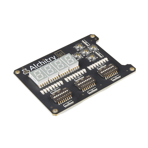
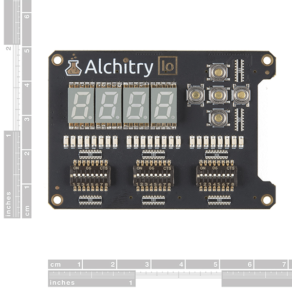
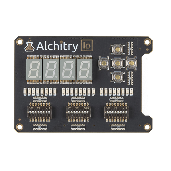
The Alchitry Io Element Board is the perfect way to get your feet wet with digital design. The Io features four 7-segment LEDs, five momentary push buttons, 24 basic LEDs, and 24 DIP switches that all lend themselves to fantastic beginner tutorials that will walk you through all the basics of FPGAs.
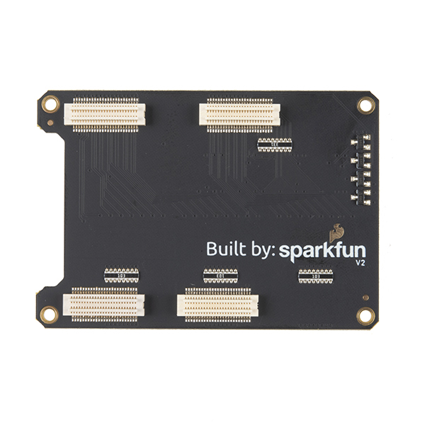
Alchitry Elements are expansion boards similar to shields for an Arduino or HATs for a Raspberry Pi but these are meant for your Au and Cu FPGA Development Boards. This Element is equipped with four connectors on the underside of the board that snap to an Au or Cu board. Be aware that the Io does not feature any connection points on the top of the board so you won't be able to stack any additional Elements on top of it.
On this most recent revision (v2) external pull up capabilities for the R12 resistor were removed
- 4x 7-segment LED digits
- 5x momentary push buttons
- 24x LEDs
- 24x DIP switches
Alchitry Io Element Board Product Help and Resources
How Does an FPGA Work?
July 30, 2020
The What, How, Why, and When of Field Programmable Gate Arrays, aka FPGAs
First FPGA Project - Getting Fancy with PWM
July 30, 2020
An initial project using Alchitry's onboard FPGA to manipulate PWM
External IO and Metastability
July 30, 2020
Why external signals can cause metastability and how to use constraint files to manage this
Programming an FPGA
July 30, 2020
Come look at the basics of working with Field Programmable Gate Arrays.
Core Skill: Programming
If a board needs code or communicates somehow, you're going to need to know how to program or interface with it. The programming skill is all about communication and code.
Skill Level: Experienced - You will require a firm understanding of programming, the programming toolchain, and may have to make decisions on programming software or language. You may need to decipher a proprietary or specialized communication protocol. A logic analyzer might be necessary.
See all skill levels
Core Skill: Electrical Prototyping
If it requires power, you need to know how much, what all the pins do, and how to hook it up. You may need to reference datasheets, schematics, and know the ins and outs of electronics.
Skill Level: Rookie - You may be required to know a bit more about the component, such as orientation, or how to hook it up, in addition to power requirements. You will need to understand polarized components.
See all skill levels
Comments
Looking for answers to technical questions?
We welcome your comments and suggestions below. However, if you are looking for solutions to technical questions please see our Technical Assistance page.
Customer Reviews
3 out of 5
Based on 4 ratings:
everything arrived well and fast, but the I/O board some leds do not work, the COM port works with archi lab, but not I can get it to work with icestudio and verilog from other sites ;
Sorry to hear you are experiencing some issues with the product. Feel free to submit a return here and we will take care of it: https://www.sparkfun.com/returns
Not good
Board is good quality, but came with 2 broken 7 segment displays. Requested a refund and support is slow to respond.
How long was the turn-around for support? Very rarely is it more than a few days...are things underway to get it remedied?
Incompatible with Qwiic connector
At rev 2, I haven't had any build quality issues like the other reviewers. It could have been handy as a display or control for Qwiic devices but the Qwiic I2C pins are unusable for I2C while the Io board is connected.
The SDA and SCL pins on the FPGA board's Qwiic connector are also connected to A23 and A24 through the bank A connector. The Io board re-uses these to drive the two left-most LEDs in the center group under the digits. The pins are connected directly to the LEDs, then to 330 ohm resistors to ground, so it's effectively a strong pull-down. I2C needs a weak pull-up and signals with a stronger pull-down so the bus is effectively jammed.
This is especially disappointing given that there are tens of dead end pins in the bank C and bank D connectors. A future board rev could use some of these instead of compromising the Qwiic connector. There's a lot of room on the back where the extra pins could have been pads for bonus hacking if nothing else.
It's salvageable for I2C by removing the two LEDs if you don't mind having 8, 6, and 8 LEDs across the middle row. To confirm which two, erase the FPGA, connect a Qwiic device with a pull-up, and turn the lights out. With the FPGA pins at high impedance, the I2C pull-ups complete the circuit to drive the two LEDs to glow faintly.
Good, with some reservations
The board itself works fine, and the example code compiles correctly and works with the iCEcube2 toolchain in the Alchitry Labs IDE. However, if I try to use the open source toolchain, IceStorm, the build fails with errors during the PNR phase. I tracked this problem down to the IDE using the deprecated arachne-pnr tool instead of the currently supported nextpnr-ice40. If I use nextpnr-ice40 in a standalone build script, then the open source toolchain works fine.
Is the "Alchitry Cu and Io Pulldown Resistors" problem (see forums or review for old version of this board) fixed? My attempt at understanding the rev-2 2021-10-26 schematic would suggest things are still wired to VCC