SparkFun Qwiic Directional Pad
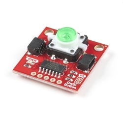
The SparkFun Qwiic Directional Pad adds a 5-way directional pad to your I2C bus!
Helpful Documentation
Product Overview
The SparkFun Qwiic Directional Pad adds a 5-way directional pad to your I2C bus! When connected to a microcontroller, press down on the directional pad (up, down, left, right, or center) to provide additional input for your application. The built-in RGB status LED provides visual feedback indicating which button is pressed.
Populated on the board is a low profile, 5-way directional pad. Each pad includes a momentary push button read by the PCA9554 8-bit I2C I/O expander and notifies the microcontroller when a button is pressed. The microcontroller will then provide visual feedback by writing to the non-addressable RGB LED. Each channel of the RGB LED can be disconnected from the PCA9554's GPIO and connected to a different input. An interrupt pin is also broken out to notify your microcontroller when a state has changed quickly. We've also included an LED for power. Utilizing our handy Qwiic system, no soldering is required to connect it to the rest of your system. However, we still have broken out 0.1"-spaced pins if you prefer a breadboard
If you need multiple Qwiic Directional Pads for your project, fear not! Each board has a configurable I2C address, so you can daisy-chain multiple Directional Pads over Qwiic and address each individually.
We've written a basic example for the Qwiic Directional Pad in our GitHub Hardware repository. You will need the SparkFun I2C Expander Arduino Library to read or write to the PCA9554's eight separate I/O pins. You can download the library through the Arduino library manager by searching 'SparkFun I2C Expander Arduino Library', or you can get the GitHub repo as a .zip file and install the library from there.
This board is great for projects requiring additional input buttons. Add a Qwiic Directional Pad to your project when navigating a menu, or even add it to a small remote to control a robot!
Features & Specs
- Input voltage: 3.3V
- Directional pad
- PCA9554 8-bit I2C I/O expander
- 2x Horizontal Qwiic connectors
- 2.2kΩ I2C pull-up resistors
- Breakout PTHs
- GND: Ground
- 3V3: 3.3V
- SDA: I2C Data
- SCL: I2C Clock
- INT: Interrupt, active low
- 5: GPIO5
- 6: GPIO6
- 7: GPIO7
- LEDs
- RGB non-addressable status
- Red power
- Jumpers
- Power LED: PWR
- GPIO7/Red LED: 7
- GPIO6/Green LED: 6
- GPIO5/Blue LED: 5
- I2C pull-up resistors: I2C
- I2C selectable address (ADR2, ADR1, ADR0)0x20 (Default): 000
- 0x21: 001
- 0x22: 010
- 0x23: 011
- 0x24: 100
- 0x25: 101
- 0x26: 110
- 0x27: 111
- Board Dimensions: 1.0in. x 1.0in. (25.4mm x 25.4mm)
- Weight: 2.60g
Customer Reviews


 Hookup Guide
 Schematic
 K1-1210UN Directional Pad Datasheet


