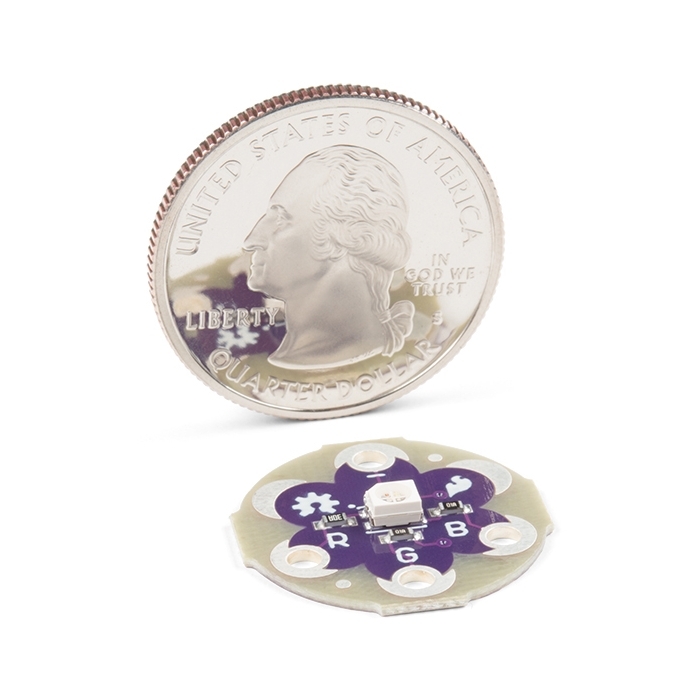
LilyPad Tri-Color LED

Blink any color you need! Use the Tri-Color LED board as a simple indicator, or by pulsing the red, green, and blue channels, you can create any color. Very bright output. This is a common anode design - to turn on a channel you simply need to ground one of the R/G/B pins to illuminate that channel.

LilyPad is a wearable technology developed by Leah Buechley and cooperatively designed by Leah and SparkFun. Each LilyPad was creatively designed to have large connecting pads to allow them to be sewn into clothing. Various input, output, power, and sensor boards are available. They're even washable!

Note: A portion of this sale is given back to Dr. Leah Buechley for continued development and education of e-textiles.

  • 20mm outer diameter
  • Thin 0.8mm PCB

LilyPad Tri-Color LED Product Help and Resources

LilyPad Tri-Color LED Hookup Guide

April 20, 2018

Learn how to hook up the LilyPad Tri-Color LED and use a common anode RGB LED in e-textile projects.

Resources and Going Further

Check out the activity guide's Arduino code and examples using a LilyPad Simple Board with the LilyPad TRi-Color RGB LED:


Core Skill: DIY

Whether it's for assembling a kit, hacking an enclosure, or creating your own parts; the DIY skill is all about knowing how to use tools and the techniques associated with them.

1 DIY

Skill Level: Noob - Basic assembly is required. You may need to provide your own basic tools like a screwdriver, hammer or scissors. Power tools or custom parts are not required. Instructions will be included and easy to follow. Sewing may be required, but only with included patterns.
See all skill levels


Core Skill: Electrical Prototyping

If it requires power, you need to know how much, what all the pins do, and how to hook it up. You may need to reference datasheets, schematics, and know the ins and outs of electronics.

2 Electrical Prototyping

Skill Level: Rookie - You may be required to know a bit more about the component, such as orientation, or how to hook it up, in addition to power requirements. You will need to understand polarized components.
See all skill levels


Comments

Looking for answers to technical questions?

We welcome your comments and suggestions below. However, if you are looking for solutions to technical questions please see our Technical Assistance page.

  • Member #207278 / about 14 years ago / 2

    Hey Sparkfun is it possible to get an update when the issues are resolved with these?

  • Member #324888 / about 11 years ago / 1

    Is there a datasheet? thanks!

  • Member #355510 / about 12 years ago / 1

    My Tri-Color LED came with the proto kit. The colors do not mix well at all. Their RGB value is just the opposite of what is should be. Another words when Red=255 it is off and RED=0 turns the red on. It seems to work the best if you just want to show one of the three distinct colors at a time.

    • Read the description again. It's a common anode LED. To light up red, connect the red pin to ground so the current you're supplying to the + pin can flow through the red LED. (For example, with Arduino use digitalWrite(redLedPin, LOW);)

      • I should have continued on to say that calling analogWrite(redLedPin, 128); would (due to PWM) reverse-bias the red LED 50% of the time, causing it to be (roughly) half as bright. This is because when a diode is reverse-biased, no current flows through it. Makes sense?

  • KirAsh4 / about 13 years ago / 1

    Has there been any progress made on these, related to the problems listed above? It's been almost two months now ...

  • KirAsh4 / about 14 years ago / 1

    I got five of these today and hooked them up to the Lilypad ... for some reason the green channel is pretty low in brightness compared to the red or blue. Has anyone else experienced this? The Lilypad is running at 5V. Makes it really hard to get color blending when the red and blue are over powering the green channel. I can't get yellow out of them, nor a bright green. I tested all five and got the same result. Tried different pins on the Lilypad, no difference.

    • Member #207278 / about 14 years ago / 1

      I am having the same problem. Following the tutorial here: http://web.media.mit.edu/~leah/LilyPad/06_rgb.html
      green is much much dimmer than the other colors and none of the output colours end up matching what is expected by her code. I tried different values and it looks like setting red and blue to around 10, while green is at 255 is closest to being equal. Makes this a bit unusable for me unfortunately.

      • KirAsh4 / about 14 years ago / 1

        I e-mailed tech support just now. Hoping to get a response soon. And yes, you're absolutely correct. I have to bring red down to 25-30 and leave green at 255 to get a respectable yellow out of it. Same for cyan (blue is at 25). I have to bring both red and blue down to that level to have their brightness comparable to that of the green channel. That makes them absolutely useless for me.

        • Member #207278 / about 14 years ago / 1

          would love to hear what they say!

          • KirAsh4 / about 14 years ago / 1

            Best I can tell you is that the response I received was that they did check and also noticed the large difference in brightness and are now trying to find out form the supplier if these are possibly bad. For now there is no resolution, so I will be sending mine back to SFE for a refund.

  • JopieK / about 14 years ago / 1

    I added support of this part to the Fritzing custom libary. You can download it at the Fritzing code site:<br />
    http://code.google.com/p/fritzing/issues/detail?id=875<br />
    <br />
    Have fun with it.

  • areadan / about 15 years ago / 1

    has anyone tried to create mixed colors with this? any tips in arduino code? it seems like giving each color the same 'brightness' does not correspond to an equal output of brightness.

    • Yep, each color LED has a different chemistry, and produces a different amount of light per input current.

    • krisiv / about 13 years ago / 1

      Use analogWrite(pin, {0:255}). Look at the RGB value as intensity where the LED is brightest as it approaches 0 (voltage goes up) and off at 255. You 'mix' colors by playing with the three intensities. Even at 240ish you see influence so by the time you are down in the 100s across all three colors you will likely just see white. Try Red at 220, Green at 0, and Blue at 255 and you will probably get a nice Yellow. A piece of clear plastic over the top helps diffuse the color.

  • bikeNomad / about 15 years ago / 1

    It depends on the power supply voltage. At 5V, assuming typical forward voltage drops (2.0V for red, 3.5V for green and blue), and typical on resistance for an Atmel output pin of maybe 25 ohms (assuming 5V supply voltage), you'd be looking at (5.0-3.5)/(100+25) = 12mA for the green and blue LEDs, and (5.0-2.0)/(200+25) = 13.3mA for the red LED.

  • Adrian3 / about 15 years ago / 1

    anybody know what the current draw on these are? trying to calculate power requirements...

Customer Reviews

3 out of 5

Based on 2 ratings:

Currently viewing all customer reviews.

1 of 1 found this helpful:

Works as intended

So this is a great little LED. It is kind of weak but what do you expect for the price. Also make sure you look at the schematic. This device is normally off so a high to one of the pins will make the LED off.

Not very bright

The light produced from the LED is incredibly dim.

Hello!

Sorry to hear about the dim LEDs. Have you contacted our technical support department @ techsupport@sparkfun.com - they may be able to help get you a replacement that's brighter or help figure out how to get the LEDs to be a bit brighter. These LEDs are normally not particularly dim.