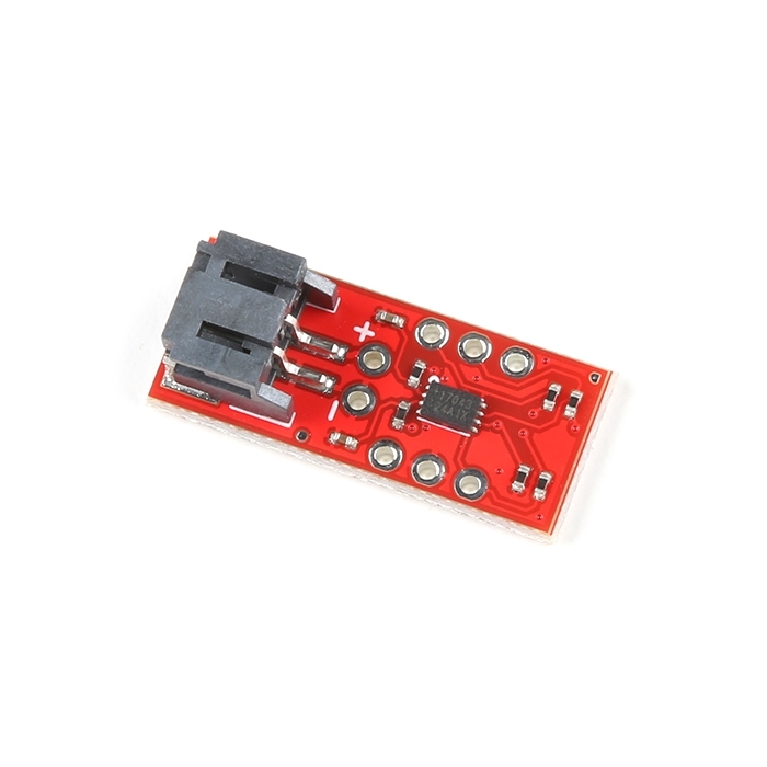
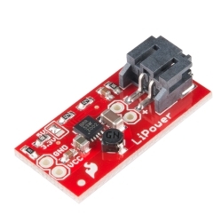
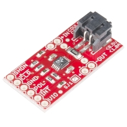
SparkFun LiPo Fuel Gauge
The LiPo Fuel Gauge communicates with your project over I2C and an alert pin also tells you when the charge has dropped below a certain percentage.
Helpful Documentation
 Hookup Guide
 Schematic
 Datasheet (MAX17043G+U)
Product Overview
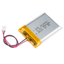
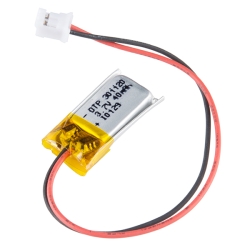
LiPo batteries are a great way to power your projects. They're small, lightweight, and pack a pretty good punch for their size. Unfortunately, even the best batteries eventually run low on power and when they do it's often unexpected (and at the worst time). Don't be caught by surprise next time your board suddenly powers-down! The SparkFun LiPo Fuel Gauge connects your battery to your project and uses a sophisticated algorithm to detect relative state of charge and direct A/D measurement of battery voltage. In other words, it tells your microcontroller how much 'fuel' is left in the tank. The LiPo Fuel Gauge communicates with your project over I2C and an alert pin also tells you when the charge has dropped below a certain percentage.
Features:
- Fuel gauge system for single cell lithium ion batteries
- Can be connected in circuit to monitor battery.
- Hardware and Software Reset.
- I2C Interface
Documents:
- Schematic
- Eagle Files
- Datasheet (MAX17043G+U)
- Example Code
- GitHub


Features & Specs
- Fuel gauge system for single-cell lithium-ion batteries
- Can be connected in circuit to monitor the battery.
- Hardware and Software Reset.
- I2C Interface
Customer Reviews

Stock and Customer Discounts
Available Discounts
- $13.25 | 10+ units
- $12.56 | 25+ units
- $11.86 | 100+ units