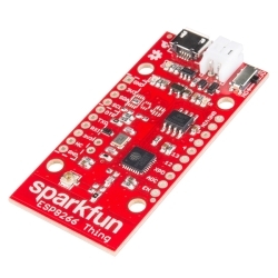
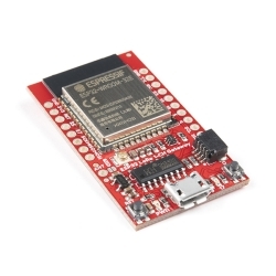
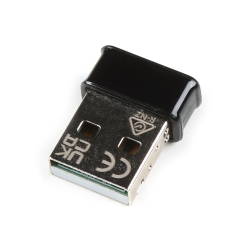
WiFi Module - ESP8266

The ESP8266 WiFi Module is a self contained SOC with integrated TCP/IP protocol stack that can give any microcontroller access to your WiFi network. The ESP8266 is capable of either hosting an application or offloading all Wi-Fi networking functions from another application processor. Each ESP8266 module comes pre-programmed with an AT command set firmware, meaning, you can simply hook this up to your Arduino device and get about as much WiFi-ability as a WiFi Shield offers (and that's just out of the box)! The ESP8266 module is an extremely cost effective board with a huge, and ever growing, community.

This module has a powerful enough on-board processing and storage capability that allows it to be integrated with the sensors and other application specific devices through its GPIOs with minimal development up-front and minimal loading during runtime. Its high degree of on-chip integration allows for minimal external circuitry, including the front-end module, is designed to occupy minimal PCB area. The ESP8266 supports APSD for VoIP applications and Bluetooth co-existance interfaces, it contains a self-calibrated RF allowing it to work under all operating conditions, and requires no external RF parts.

There is an almost limitless fountain of information available for the ESP8266, all of which has been provided by amazing community support. In the Documents section below you will find many resources to aid you in using the ESP8266, even instructions on how to transforming this module into an IoT (Internet of Things) solution!

Note: The ESP8266 Module is not capable of 5-3V logic shifting and will require an external Logic Level Converter. Please do not power it directly from your 5V dev board.

Note: This new version of the ESP8266 WiFi Module has increased the flash disk size from 512k to 1MB.

  • 802.11 b/g/n
  • Wi-Fi Direct (P2P), soft-AP
  • Integrated TCP/IP protocol stack
  • Integrated TR switch, balun, LNA, power amplifier and matching network
  • Integrated PLLs, regulators, DCXO and power management units
  • +19.5dBm output power in 802.11b mode
  • Power down leakage current of <10uA
  • 1MB Flash Memory
  • Integrated low power 32-bit CPU could be used as application processor
  • SDIO 1.1 / 2.0, SPI, UART
  • STBC, 1×1 MIMO, 2×1 MIMO
  • A-MPDU & A-MSDU aggregation & 0.4ms guard interval
  • Wake up and transmit packets in < 2ms
  • Standby power consumption of < 1.0mW (DTIM3)

WiFi Module - ESP8266 Product Help and Resources

ESP8266 Powered Propane Poofer

March 15, 2016

Learn how Nick Poole built a WiFi controlled fire-cannon using the ESP8266 Thing Dev Board!

ESP8266 Thing Hookup Guide

May 21, 2015

An overview of SparkFun's ESP8266 Thing - a development board for the Internet of...Things. This tutorial explains the circuitry driving the board, and how to get it up and running in an Arduino environment.

ESP8266 AT command reference

There is a great ESP8266 command reference at this link.


Core Skill: Programming

If a board needs code or communicates somehow, you're going to need to know how to program or interface with it. The programming skill is all about communication and code.

2 Programming

Skill Level: Rookie - You will need a better fundamental understand of what code is, and how it works. You will be using beginner-level software and development tools like Arduino. You will be dealing directly with code, but numerous examples and libraries are available. Sensors or shields will communicate with serial or TTL.
See all skill levels


Core Skill: Electrical Prototyping

If it requires power, you need to know how much, what all the pins do, and how to hook it up. You may need to reference datasheets, schematics, and know the ins and outs of electronics.

3 Electrical Prototyping

Skill Level: Competent - You will be required to reference a datasheet or schematic to know how to use a component. Your knowledge of a datasheet will only require basic features like power requirements, pinouts, or communications type. Also, you may need a power supply that?s greater than 12V or more than 1A worth of current.
See all skill levels


Comments

Looking for answers to technical questions?

We welcome your comments and suggestions below. However, if you are looking for solutions to technical questions please see our Technical Assistance page.

  • -------------------- Tech Support Tips/Troubleshooting/Common Issues --------------------

    ESP8266 WiFi Module (i.e. ESP-01)

    The ESP8266 WiFi Module is also known as the "ESP-01". There are many different models and breakout boards based on this wireless microcontroller.

    Pinout for the ESP8266 WiFi Module

    Here is a clear pinout for ESP-01 v2 [ http://playground.boxtec.ch/lib/exe/detail.php/wireless/esp8266-pinout_etch_copper_top.png?id=wireless%3Aesp8266 ]

    For the pinout for all versions of the ESP-01 V1 and V2, check here => [ https://github.com/esp8266/esp8266-wiki/wiki/Hardware_versions

    Making the ESP826 WiFi Module Adapter for Breadboards

    Try looking at this tutorial on the ESP8266 => https://youtu.be/9QZkCQSHnko . The tutorial talks about how to make an adapter for breadboards and advantages of using the WiFi module. It also talks about how to update the firmware with the ESP8266 IC.

    Additional Example Tutorials

    Serial-to-WiFi Tutorial using ESP8266: Testing the module via 3.3V FTDI => [ http://fab.cba.mit.edu/classes/863.14/tutorials/Programming/serialwifi.html ]

    ESP8266 WiFi module and 5V Arduino connection => [ http://iot-playground.com/blog/2-uncategorised/17-esp8266-wifi-module-and-5v-arduino-connection ]

    Using the ESP8266 to add Wi Fi to the mbed LPC1768 => [ https://developer.mbed.org/users/4180_1/notebook/using-the-esp8266-with-the-mbed-lpc1768/ ]

  • bobdabiulder / about 8 years ago / 2

    Simple setup guide: https://docs.google.com/document/d/1JBBhZbJQj-1B9JWC4t8alLh9n6vaC8XrYgasOVeQVhc/edit?usp=sharing

  • jonahbron / about 4 years ago * / 1

    There is a NodeJS interpreter available for the ESP called Espruino.

    https://www.espruino.com/

    I ran into some slight configuration difficulties, but was able to figure it out. I posted about it on their forum with the exact command I used to flash the firmware to mine. It works great!

    http://forum.espruino.com/conversations/347599/

    I also strongly recommend using the Definitive Wiring Guide instructable.

  • Member #500723 / about 6 years ago / 1

    I have 3 of these from Decembr 2017 and one just this week. They all 3 still only show 512K available. When the site says the NEW ones are 1Mb. What is up? Am I missing something?

  • Member #500723 / about 6 years ago / 1

    Just got my little ESP8266 wifi modules. Powering these things up properly is an understatement. Very finicky. Even after finally uploading a sketch successfully, the only light I ever see on both boards mind you, is the blue LED during sketch upload. NO RED power light ever comes on.

    I have powered these from use of the suggested USB to TTL cable that Sparkfun supplies. Using the VCC into a 3.3V voltage divider = NO GO Powered from a wall wart via regulated 5V with a 3.3V voltage divider = NO GO The only thing making these work, is using the 3.3V from a powered up Arduino Uno which is powered via a USB cable. = STILL NO RED LED

    Also, when uploading a sketch, I have to remove power and the serial connection before uploading a new sketch every time. Not a big deal, but thought Id make note of it. Im using the following pinout and all works. Have been able to create an access point, scan for wifi access points, and send data to an MQTT server. So once you get this lil guy running, you will be pleased!

    -- ESP8266 module -- 3v3 --> 3v3 from Arduino Uno EN (chip select) --> 3v3 from Arduino Uno GND --> GND from Arduino Uno GPIO0 --> GND from Arduino Uno Rx --> Tx of USB to TTL cable Tx --> Rx of USB to TTL cable

    • please note, I have a 16V 470uF cap on my power ahead of the power going to the ESP8266.

    Has anyone else had the same issue of NO RED LED? If so, did you fix it? Do these just not have one, despite the doc saying they do?

    Thanks and good luck!

  • Sagar / about 7 years ago / 1

    Is it possible to directly program the ESP8266 instead of accessing its functionality from the AT command set? Ie. can I use it as a generic microcontroller as well as a wifi module? I believe this is possible if GPIO15 is tied to ground as described in this post: https://hackaday.com/2015/03/18/how-to-directly-program-an-inexpensive-esp8266-wifi-module/

  • xxyeiroxx / about 7 years ago / 1

    Hello there! One question. Can these guys run on a 3V Coin Cell? Cheers.

  • This thing is great! I flashed a basicinterpreter in it, so it is simply programmable in oldschool basic.

    :-)

  • We created a simple tutorial for connecting ESP8266 to Arduino Uno software serial. We'd love your feedback >> ESP Arduino Uno integration

  • Member #483244 / about 8 years ago / 1

    It seems the board is very fruitful. Especially when it comes to power consumption. But how to upload software logic on it? I'd like to use 2 built in GPIOs. Can I upload adruino sketchup on it?

  • Member #746982 / about 8 years ago / 1

    If I am going to connect this to either an Arduino or a 32-bit microcontroller, what is the size of the information which I can send or receive using this chip?

  • submission / about 9 years ago * / 2

    Yes the ESP8266 will connect to a Cell Phone , I can connect to it through either my Android , iPhone , home wifi router or laptop in either a direct connection or AP mode

    I flashed the ESP8266 with LUA using ESPlorer and set it up as a server .

    Here is the code I use to send and receive data to/from wifi / usb.

    uart.setup(0,9600,8,0,1,0)
    sv=net.createServer(net.TCP, 1800)--1800=30min timeout.
    global_c = nil
    ip=wifi.sta.getip()
    print("?")
    print(ip)
    print("/")
    
    sv:listen(9999, function(c)
    if global_c~=nil then
        global_c:close()
    end
    global_c=c
    c:on("receive",function(sck,pl) print(pl) end)
    end)
    
    uart.on("data",0, function(data)
        if global_c~=nil then
            global_c:send(data)
        end
    end, 0)
    

    • Thanks for the sameple script - in your code above can you tell me what this returns? ip=wifi.sta.getip()

  • bobdabiulder / about 9 years ago / 1

    Where can I find a library

  • PalmTreesandPICs / about 9 years ago / 1

    What is the pinout for this? there are several versions out there with different pinouts. some of them have the mid 4 pins (2 top+2 bottom) as "NC"... at least on the links provided.

  • Member #226770 / about 9 years ago / 1

    Instructions for getting started with the ESP8266 using the mbed LPC1768 are available at https://developer.mbed.org/users/4180_1/notebook/using-the-esp8266-with-the-mbed-lpc1768/

  • I’ve used the previous .5MB version and now this new 1MB version. I also added a review of this module spanning both versions. My first use of this module was with a 3.3v USB to serial connected directly to the module. As I mentioned in my review it was rock solid. Next I moved on to controlling it with a PIC micro-controller, I wasn’t having much luck as they seemed to keep rebooting due to watch dog or crash with exception dumps. They would also get very hot and the Red LED would get very dim. I was getting very close to contacting Sparkfun tech support that these modules have an issue, however if I put them back connected directly to the USB to serial they worked fine. At that point I decided it must be something to do with the power and I hooked up the ESP8266 with its own 3.3v regulator and I am happy to report these modules are as solid as when hooked directly to the USB to serial interface. It doesn't matter how much current your 5V source can supply to your regulator, this module seems to be either sensitive to noise and or it uses power in surges for the transmitter and if the voltage momentarily drops the board goes into some sort of latch up condition. If you see resets and the power LED going dim, try a dedicated regulator, you'll be glad you did.

    IMPORTANT: If you want to keep your sanity when working with these on a breadboard, supply power to them with their own 3.3v regulator, probably not a bad idea to do the same when making a PCB board either.

    Also most people seem to use this module with TCP connections. I am using it with UDP sockets and there isn’t a lot of information out there. If you need information on using UDP sockets check out this series of articles I have published on a prototype I am creating using the ESP8266 with UDP. Also you can check out my Google+ collection on the ESP8266 prototype here.

  • Chapel / about 9 years ago / 1

    Does anyone know if this has any regulatory certifications (FCC,RSS,etc)?

  • Member #57704 / about 9 years ago / 1

    Module overheats and no data communications; crashes mcu when powered on.

    • Member #461332 / about 9 years ago * / 1

      I've discovered that if you put a ~2k resistor between the CH_PD and power, the board stays significantly cooler. I used to get nervous running mine, so I constantly had a fan blowing on it, but after I read several tutorials recommending the use of a resistor, it's been fine since then. It still gets warm, but not burning. I'm pretty sure the resistor I had on it was a 2k, but I'm sure if you experiment around with different resistances you'll find one that works for you.

      Also, make sure you are using 3.3v everywhere, since the board is not 5v tolerant.

      -This is all assuming you don't in fact have a defective board. :) Good luck!

    • M-Short / about 9 years ago / 1

      Sounds like you might have a bad board. Email techsupport@sparkfun.com and they should be able to help you out.

      • Member #57704 / about 9 years ago / 1

        All 3 purchased do the same thing. Even with their own 3 amp power supply, gets hot enough to burn skin. Overheats power supply too.

        • M-Short / about 9 years ago / 1

          In that case it might be something with your set up. Email techsupport with a description of your setup and what you are seeing and if possible include a picture of your setup and they should be able to help.

  • Member #57704 / about 9 years ago / 1

    What is the pin-out for the module?

    • http://playground.boxtec.ch/lib/exe/detail.php/wireless/esp8266-pinout_etch_copper_top.png?id=wireless%3Aesp8266

  • Can this device support WiFi Direct connections to a mobile phone? If so, where can I find an example?

    • SynapseRapture / about 9 years ago / 2

      If your phone can act as a hotspot, you can configure the ESP8266 to connect to your phone's SSID. If not, you can set up the ESP8266 as an AP and connect your phone to it. In either case, there is a wealth of knowledge in the ESP8266 Community Forum at www.esp8266.com.

      • Thank you for the information. Would you know if the ESP8266 can have its IP address pre-set - so each time it boots up it uses the same IP?

        • Member #461332 / about 9 years ago / 1

          It can! If you have your ESP connect to a wifi network, it can/will have both a dynamic and static IP. There's also an AT command to set your own static IP. I apologize I don't remember off the top of my head, but www.esp8266.com is where I'm finding most of my information.

Customer Reviews

3.8 out of 5

Based on 39 ratings:

Currently viewing all customer reviews.

13 of 13 found this helpful:

The Little Module that could, and probably will!

UPDATE: I've used the now retired .5MB version and this version. Below I have put a copy of my original review. Since posting that I moved past just controlling it via a USB to Serial interface and put it on a breadboard with a microcontroller and I found this to be important: Use a dedicated 3.3v regulator to power this module, see my comment in the comments section about this.

PAST REVIEW: A lot of bang for the buck! Overall it’s a pretty solid little board. It comes preloaded with firmware that implements an AT command interface. I recommend updating to the latest AT command firmware, especially if you are going to use UDP mode of communication.

I haven’t used it with TCP connections, but the UDP mode seems to be very robust. I’ve had it running for over 3 days sending UDP packets every 2 seconds and it’s still going strong, no hiccups with WiFi connection or serial data transmission to and from the module. I’m sure my awesome software design and coding has something to do with it, but the module is holding its own :)

Range seems pretty good, I had no problem connecting to my router indoors from anywhere inside, and I even took my setup on a breadboard out to the furthest point in my yard, about 150 feet from the house and was able to connect to my router down in the basement through solid concrete poured foundation. Not too shabby.

Since they are so economical I bought 2, and I’m glad I did, as the description mentions do not hook this up to more than 3.3 volts. When I went to update my firmware on one of the boards I didn’t have my glasses on and inadvertently connected the GPIO0 to USB 5v rather than ground the next terminal over. When I noticed the mix-up I switched it to ground and successfully flashed the new image, but when I try to boot up normal it just spews garbage out of the serial port, so it is very sensitive to the wrong voltage.

I don’t have any issues with the board, but I can’t bring myself to give it a 5 star rating as I believe that should be saved for special circumstances, even though this module is lots of bang for the buck I feel like there could be a better ESP8266 board so I’ll call it a 4.5 and recommend you play around with one if you haven’t already.

3 of 3 found this helpful:

Works fine

RX TX pins were reversed for me at least if you go by NURDSpace. I connected the pin labeled RX to TX on my Arduino and TX to RX (all through level shifter) and it didn't work, I switched the pins RX to RX and TX to TX and now it works.

Works great now that I've straightened that out, I was ready to ask for return on a defective module.

2 of 2 found this helpful:

Great WiFi module, works with lots of services

The community has really come together to make this inexpensive module easy and (relatively) reliable. I like the Arduino port, because it's easy and works with a whole mess of libraries, but NodeMCU is acceptable, as is the native toolchain. Works well with services like Blynk if you want to control it with a smartphone without writing a custom app and server. Definitely get it some power of its own, nearly turned my FTDI Basic to slag just teasing the NodeMCU upload.

1 of 1 found this helpful:

Good for what it does

Look. I like this module. I really do. Even though I totally fried mine after like three days. It was probably completely my fault.

I've been playing with various ESP8266 modules for a while now. This module is probably exactly what you need if you want to interface with an Arduino and chat with the pre-flashed Hayes AT-based firmware to access web pages. You know, get up and running quickly.

That said, unless you're really a fan of the AT-based firmware, I'd recommend you pass this guy up in favor of the Thing Dev board. Did you know you can upload Arduino sketches to ESP8266 modules pretty easily? But putting these guys in flash-mode is a bit of a chore, and the Thing Dev board is supposed to do that automatically (I don't have one so I haven't verified).

Also I'd prefer more GPIO than this ESP-01 module offers. The Thing would probably be better for that, but if you're looking for something more modular I might recommend just going to eBay and finding a reputable dealer for an ESP-12 or ESP-13.

6 of 6 found this helpful:

The internet, for $7!

I'll hold off on saying what you've probably already read with the words "cheap", "IoT" and "the future" and tell you what I have learned so far.

I ordered one of these in early October (2015) and was able to get it responding, however, I was thrown off by its version response. I can't speak for other suppliers, whose product images often show a more "plain" blue board, but Sparkfun sells this nifty "black AI-Cloud" (AI-Thinker) version (with possibly a larger flash than "blue" versions, which can be important later on for Firmware Over The Air (FOTA) and other firmware flashing). I believe AI-Thinker is partnered/licensed by some means with Espressif (the ESP8266 SoC maker) to make a board. I compare it to Arduino using Atmel's AVR. I mention this because support for this chip is largely community driven and it can become very confusing. You'll see that you can use AT commands initially to talk to the device and the firmware version on these is slightly different than 99% of what you will read; it seems to be AI-Thinker's version of Espressif's AT commands. The commands seem to be the same and I don't know the differences, other than the possibility that these boards get their FOTA from AI-Cloud's servers instead of Espressif's servers.

Considering the versions and the fact that these (and similar modules) are constantly being updated, the module I received was based off of

AT version 0.25 (Jun 5 2015) SDK version 1.1.1

and FOTA upgraded to

AT version 0.30 (Jul 3 205) SDK version (Build) 1.2.

Since I am brilliant I nearly broke my module and decided to then order an additional three at the end of the same month (October). I have so far only tested one of these devices and the version on it is

AT version 0.40 (Aug 8 2015) SDK version (Build) 1.3 Sep 11 2015.

Good to know these modules are up to date AND which firmware we are working with. Also important since the community will tell you these modules have varying baud rate settings, the baud on these was set to 115200.

In case you haven't figured it out yet, there are many different firmware versions out there, including third-party. Espressif has their firmware, SDK and flasher, AI-Thinker has their iterations (as I'll just call them) on Espressif's firmware, SDK and flasher. You also have NodeMCU firmware (based on the Lua programming language), micropython (based on Python), ESP Basic (based on the BASIC programming language), Espruino (based on the development board of the same name and the JavaScript language) and of course an Arduino Add-on. Very awesome that there are options, but can be another confusing thing you can come across.

If this is the first time you are working with this board, grab a 3.3V Basic FTDI, DEV-09873 $14.95, 3.3V Regulator, COM-00526 $1.95, a Bi-Directional Logic Level Converter, BOB-12009 $2.95 and some Male/Female Jumper Wires - 20/PK, PRT-12794 $1.95. The extra $22 may save you some peace of mind and can certainly be used for other projects. I did initially use the logic level converter and was able to work off of the Arduino's 3V3 pin, however, some quirks I ran into (which I believe lead to further problems) could probably have been attributed to the Arduino unable to provide the necessary current causing the module to reset. NOTE: This doesn't mean I had a problem with the module, rather the problems were very likely user related.

I did not give this module a 5 star rating because I'm still learning about this module and I'm an electronics hobbyist so my knowledge may not be as great. Therefore, I didn't think it was fair to give it a full rating if I haven't been able to use all of it's features. Yes... It's not breadboard friendly but the M/F jumper wires makes it a non-issue. Otherwise I was able to connect it to the internet out of the box and all for $7!

EDIT: Fix some formatting.

4 of 4 found this helpful:

Works great!

Running this with an Arduino Uno, using a 3.3v voltage regulator and 3.3v LLC, and it's been very stable. So far it's been 2-3 weeks, sending sensor information to a web server once per minute with almost no downtime.

1 of 1 found this helpful:

Working now, with a mod

I bought two, and I can't program them. It appears that the reset pin has not been connected to the header. Pin 32 is the reset pin on the chip and it goes to what appears to be a 10K pullup resistor and and small cap that goes to ground. But, it does not go to the pin on the header that the documentation describes. Hence, I can't program it. Waiting on tech support. I can communicate with it, but reset seems to be broken. edit 7/11/2017 Turns out tech support never got my request, but contacted me because they saw my review. I discovered that the reset line has a 12k resistor in between the pin and the micro. There also is a pull up (10K). No way to pull the reset line low, so I removed the 12k resistor and replaced it with a short. I can program the part now. Leaving my review rating as it is because the modules that I received were built wrong. Your mileage may vary. The resistor is the one closest to the header pin 1.

8 of 8 found this helpful:

So Far So Good, but Be Aware

I bought a couple of these modules last month (Nov. 2015) and when I finally got around to exploring with these, it took me a few days to get them working.

My "Be Aware" remark in the title is because this is not something that an inexperienced user will find easy to work with. A few things to point out.

The module is very picky about power. I recommend powering this with a dedicated power supply. I also recommend using a dedicated power supply along with filtering capacitors to ensure that the power is steady. When I finally got the modules to communicate, there were numerous resets. Good jumper wires and good connections to the breadboard along with filtering capacitors solved the problem.

Documentation is shall I say "not really up to speed". I have found that there are pictures of the pinouts on the internet that are wrong.

Once you do get one of these working properly... WOW! The possibilities are endless.

The only reason that I gave this 4 stars rather than 5 is because of the difficulty and frustration involved getting them to work. I must point out that my purchase from Sparkfun was a good experience as always, and they did have tech support on hand to help me out.

2 of 2 found this helpful:

Neat gadget at an amazing price, tricky setup

It's amazing that this board provides the level of Wi-Fi and TCP/IP functionality for the price. That said, it is tricky to get started using the device. I found that my module did not work properly until the CH_PD pin was pulled up to VCC. The Nurdspace page that is linked from the product page doesn't list this pin. I also found that I had to flash the device before it worked properly. I'm not sure if it was unprogrammed when I received it or if I did something to mess it up while trying to get it connected properly.

I found this website extremely useful as a reference for flashing the board and for many other odds and ends: http://labdegaragem.com/forum/topics/conhecendo-o-esp8266 Note that this board (or equivalent) is named ESP8266-01. The website is in Portuguese but Google Translate did an excellent job and it's quite readable after being translated. I achieved first-time success in flashing the board by following the instructions on this page.

One other thing--the page I linked as well as some forum posts note that PuTTY and Tera Term don't agree with the ESP8266. A free utility, TERMITE (linked from the above page) worked well with it.

2 of 2 found this helpful:

Good product for the price

It's a very good product and I'm having tons of fun with it. However, as mentioned in previous comments, you need to be patient when you try to connect it the first time. There are all sorts of things that can go wrong and here's what I found until it worked properly.

1) Power Supply: make sure to provide enough juice to the module and to apply a large filtering capacitor between its VDD and GND (1uF worked for me).

2) Pinout: the pins I found in the websites provided were correct except for at least one that was ignored. The image you may find (top view) look like this

(Antenna on Top)

GND_ NC NC _Rx

TX_ NC NC _VCC

But at least one of the "NC" should be connected during setup. It's called CH_PD. This pin has to be pulled-up to VCC to enter AT command mode. You pull it down to GND to be able to change the firmware (didn't try it yet). So the pins now look like this:

(Antenna on Top)

GND_ NC NC _Rx

TX_ CH_PD NC _VCC

3) Baud Rate: the baud rate or this device is verified as described to be 115200. But if you get one from other vendors, the firmware version might be different with a different baud rate.

4) Terminal Program: I used my pc to connect to the device. There seems to be data encoding issues with some terminal programs. Tera Term didn't work for me so I switched to one some people suggested called TERMITE (it's actually cool). I setup everything and finally got a response for my "AT" command. But it was always showing "ERROR". I fixed this after changing the settings of Transmit and Receive in TERMITE to "CP + LP" (the default comes either CP or LP only).

With all this it worked well and I was able to communicate with it and configure its network connection later.

2 of 3 found this helpful:

I bought two and could never get them to work

I've seen the other reviews and searched the internet along with contacting help at Sparkfun. However, I could never get them to work. The module only returns garbled text when sent an AT command. All the snippets of help said the same thing, that it is either power issue or baud rate. I have provided its own power supply at 3.3 with 1amp. I have tried all baud rates. I even tried to manually change the baud rate by sending the proper AT command to do that and I still could not get anything readable.

1 of 2 found this helpful:

ESP8266_NO_GOOD

Hi, The Sparkfun ESP8266 WiFi Module doesn't work correctly, it can't connect to Hostpot (AP WiFi) neither to the STA WiFi, it takes too much time, is not reliable to all.

Personally I usually buy from Digi-Key, not from your website directly, Digi key Part Number 1568-1235-ND, Manufacturer SparkFun Electronics Manufacturer Part Number WRL-13678

Your Module is low quality compare to Digi-Key Part Number 1597-1145-ND Manufacturer Seeed Technology Co., Ltd Manufacturer Part Number 317060016

This is working perfectly.

Why did I buy directly from your website? Is because after wasting 100 pcs of your Modules, I decided to buy from your website maybe the quality can be better than the one you have on Digi Key. This is why I bought 10 pcs for a test directly from you website, your modules are not working at all.

The other manufacturer Module works perfectly without giving any connection problems I bought from Digi Key lot of modules, unfortunately the modules were sold out by the moment I wanted to order.

Best Regards

If you're having technical issues with these, please contact our technical assistance team for help.

1 of 2 found this helpful:

It works great.

These modules are easy and powerful.

Arduino newbie

Module came quickly in great condition, I'm having a little trouble getting it online but I blame my news status to arduino and coding not the product. I would definitely recommend it if you are in the market for adding wifi to a project. It can also be set up as a stand alone controller which I find really cool. The main downside is the inability to convert logic signals from 5 to 3.3v onboard so you have to use a logic level converter. Overall a great wifi option!

Holy moley, this thing is amazing!

I've never worked with anything over serial yet, but holy smokes was this thing easy to setup. Right now I'm just messing with it through the Serial Monitor via an arduino, and it was able to seamlessly list all networks around. Connect to my wifi. And accept all the commands with zero problems. I'm so impressed with this thing, I think I'm going to buy lots more. The possibilities are endless here!!

Very impressed

Worked well, was deliverered fast, and had the pinout printed directly on the module (made for easy setup)

Nice module, documentation a little lacking

I am using this module with esp-link to connect to a HY-TinySTM103T running mecrisp-stellaris forth. I initially had trouble flashing firmware onto the board until I discovered that the flash mode had to be set to 'dio' or 'dout' rather than 'qio' (the default in many cases). None of the documentation listed on the sparkfun site indicates this, I had to determine it experimentally.

Works great

I read from some other articles regarding stability issue and restarting frequently; but it didn't happen for me. I really appreciate using this module. Have fun guys!

Good tool!

  • DCF77 replacement with NTP
  • GPS - $GPRMC replacement with NTP

Great part! Easy to use, fun to program.

So the ESP8266 was a little difficult to get linked up all right. There are tons of conflicting bits of documentation all for different flavors of the ESP8266. I successfully used this guide for the "Thing", but it worked perfectly: https://learn.sparkfun.com/tutorials/esp8266-thing-hookup-guide/installing-the-esp8266-arduino-addon

One of the things that wasn't super clear to me right away was that you don't actually need an arduino processor to communicate between the FTDI and the on-board processor for the ESP8266. You can flash it directly from your FTDI.

I used a simple FTDI bus with a 3V external power supply (to power the wifi module) across a 1000uF capacitor. I used 100ohm resistors on the data lines. I had no trouble damaging the circuit even though the FTDI spits out 5V on the RX/TX pins. I used the FTDI basic with the full-size USB port.

Works well, GPIO are nefarious.

This module does exactly what I wanted...connects to the WiFi and sends me an alert when an event happens. Perfect tool for tge job and good price.

The only negative thing I have to say is about the GPIOs. It is not very clear how the GPIOs work, and depending on how you use one pin, the other may not work the same way. Digging into the ESP8266 datasheet will answer these questions, but using the module's GPIOs in the Arduino IDE was not as simple as using a typical Arduino's GPIOs.

Not simple to get working

Cheap, but have yet to get them working.

Nice

A tiny rectangle of WiFi goodness

We love this little WiFi module over here at the geekpower/WhenYouFly studio. In designing a new-fangled replacement for the paper logs many private pilots keep in their airplanes we decided it needed to upload data via WiFi and thus began the search for a small, inexpensive, simple WiFi doodah that would meet our pretty straightforward requirements. We mated it to an Atmega 1284 on our own PCB and simply send it AT commands (remember those from your C64/BBS days?). We run our Atmega at 8Mhz for power reasons, so we keep the data rate between this module pretty slow (9600bps) and it works perfectly. It even has pretty good range - planes outside the hangar area up to about 200' away can upload logged data with good success. Thank you, Spark Fun!

Yes, I remember the C64 and BBS! Dialup at 1200 baud was slow, but got the job done back in those days. :-) Thank you for the review and for sharing your project!

Assistant/Associate Professor

Great product and fast shipping

Works great!

Was very satisfying to connect over serial and talk to the chip with AT commands. Pretty easy too once I got the line endings right.

Also easy to reprogram if you know what you're going. I recommend this wiring guide.

https://www.instructables.com/id/FTDI-ESP8266-Definitive-Wiring/

Awesome for Price!!!!!

This module is absolutely amazing considering the price, but it was a bit tricky to get working. This module required a bit more work than others to get working but it operates perfectly. There is not much documentation online so I would not recommend this module for beginners. Other than the huge learning curve, this module is the best wifi module on a budget.

0 of 12 found this helpful:

Terrible!

This thing, as mentioned, is "not breadboard friendly". That is a huge understatement! Not only is not not breadboard friendly, but it's back extends out too far, so it covers up and potential headers. I recommend a socket for this. Don't be like me!

PS: or put it in sideways, and IGNORE the middle pins!

We like to use some F/M jumper wires. That will allow you to adapt to the back of the ESP8266 and then plug into a breadboard. https://www.sparkfun.com/products/9140

This is a very impressive device...

...considering it's size and affordability. While it is a little buggy and potentially difficult to program without the right tools, once you get it working, it connects to your wireless network and is running your code within 6 seconds of powerup.

If you need other antennas/controller, there are other models of ESP out there, but this one is perfect for someone seeking a learning opportunity with 2 GPIO pins.

Like but fried a couple - don't know why

Have 2 now. One pulls 20 to 30 ma (no wifi state). other is pulling 93 ma. Gonna get 2 more and hope to figure it out. I'm using pic mcu to send AT commands.. 1st tried Voltage Divider for TX: eventually fried the ESP. Then tried running the PIC at 3.3v: similar result. Now using bidirectional level converter. This is the ESP pulling 93ma in no wifi state.

Wifi on the cheap.

I am attempting to use this project in conjunction with an Arduino to provide wifi connectivity to one of my projects. The devices are pretty cheap, which is good. That said, they can be a bit difficult to get to work. You will need to be comfortable with "AT" commands, and will probably want to re-flash the device to get the latest firmware. That said, they are not too bad. Note that you will probably want a usb to serial cable (FTDI) in order to update the firmware. Also, the devices are sensitive to voltages. I'm using a 3V voltage regulator and have not had issues. Good luck!

Good for simple WiFi tasks

I like these a lot. Sure, you could pay a couple extra bucks for the full breakout - and you should if your project requires more GPIO pins. However, for simple WiFi tasks that requires only a single GPIO (e.g. One-Wire), these are great. They run cooler and are smaller so they'll fit in smaller places and tighter circuits. I have many of these around the house as thermometers that report to a server that controls the air conditioner as well as servos (to open / close vents) in order to keep all of the rooms at their desired temperatures.

Keep in mind that while it has a pretty fast clock for an soc, it is extremely picky about watchdog. So, Serial IO may have you pulling your hair out due to the constant watchdog restarts. Get past this by not doing both input and output in the same bracket. I could be wrong, but I think the watchdog is fed every time the stack level is changed.

No other wifi module like it!

Not only is it a fully capable wifi module, it's MCU is fully exposed. You can construct all types of wifi net with these module e.g. Meshes. And the list of projects go on beyond wifi applications.

Returns Junk Text

I tried to get one of these to work but even with its own dedicated 3.3v power supply and after trying all possible baud rates it still only returned meaningless junk characters

Sorry you're having trouble with this board. If you'll contact our tech support team, they should be able to help you resolve the issues you're having.

Libraries

The other libraries you list provide good info but don't address this board directly. You should look at this one:

https://github.com/bportaluri/WiFiEsp

While I have not gotten everything working yet, I am much farther along.

Has issues but is amazing for the price

Connects to the network very well after issuing an inordinate number of commands that it should remember. It also requires termination characters of <cr> <lf> pairs for the commands and for data received and transmitted, both in client and server modes. There should be a mode that it just transmits and accepts characters as they are sent/received. Even in "stream" mode a <cr> <lf> pair is required ... absurd.
But if your application doesn't care the module is a great buy and works well.
Don't forget to RS232 interface chip unless going directly to a microprocessor.

Still working out how to get it going

coming from a background of trying to get the NRF24L01 module to work. Emphasis on the word "trying".

This is working with an operating system. Just rewrote it, so still going through bugs here and there. Need to debug the drivers for this, but they're simple RS-232 drivers for the OS, which should work. Past that, need to get networking/connect and perhaps RF mesh working.

So far, the chipset looks easier to use, although unless you dig for it, the higher level software is missing. If you're in an Arduino environment (and I'm not), there may be drivers out there. Since I'm not, it's roll your own time. (answer to question: Yes, the OS has enough goodies that I'll keep it, or perhaps maybe (or not) rewrite it into FreeRTOS, but FreeRTOS doesn't have things I need.)

You'll need RS-232 communication, then something to call functions to connect, then transfer messages. What you do beyond this is a function of what you decide to do overall. The creators do have software and infrastructure to look at, but I haven't done that enough yet.

Stay tuned, if I can add to this review....

So far, looks good. All the work will be up at the system level (message types, connects, dialogues between nodes...)

BOARD IN ARDUINO

IN ARDUINO WHAT BOARD I NEED TO CHOSE IN TOOL MENU

If you can't find what you need under the documents section, you can always get in touch with our tech support team. They should be able to help you out!