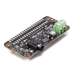
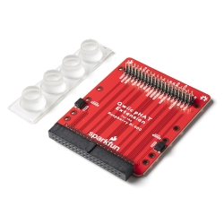
SparkFun Servo pHAT for Raspberry Pi
The SparkFun Servo pHAT for Raspberry Pi allows your Raspberry Pi to control up to 16 servo motors in a straightforward manner via I2C.
Helpful Documentation
 Hookup Guide
 Schematic
 Datasheet
Product Overview
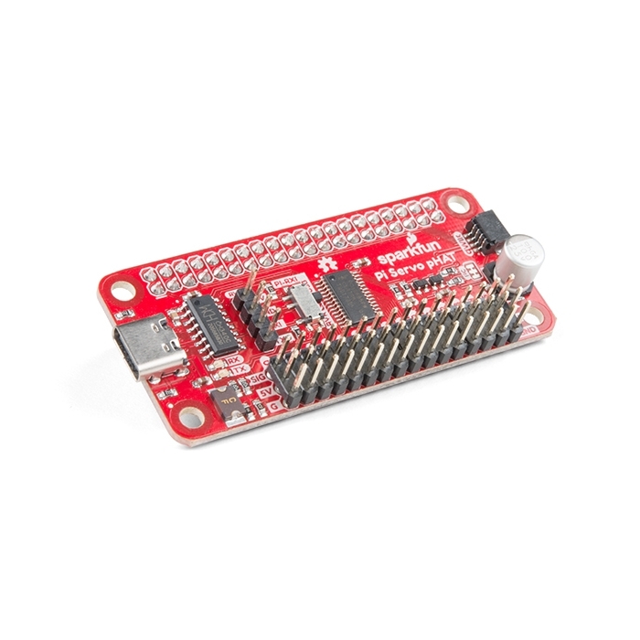
The SparkFun Servo pHAT for Raspberry Pi allows your Raspberry Pi to control up to 16 servo motors in a straightforward and uncomplicated manner via an I2C connection. Thanks to its I2C capabilities, this PWM HAT saves the Raspberry Pi's GPIO pins, allowing you to use them for other purposes. The Servo pHAT also adds a serial terminal connection, which will allow you to bring up a Raspberry Pi without having to hook it up to a monitor and keyboard. We have provided a Qwiic connector for easy interfacing with the I2C bus using the Qwiic system, and a 4-pin header specifically for connecting to the Sphero RVR.
Power to the SparkFun Servo pHAT can be supplied through USB-C connector. This will power either the servo motors only, or power the servo motors as well as the Raspberry Pi that is connected to the HAT. We switched to USB-C to allow you to bring more current to your servos than ever before. This USB-C connector can also be used to hook up the Pi via serial port connection to avoid having to use a monitor and keyboard for setting up the Pi. To supply power only to the servo power rail (and not the Pi's 5V power rail), you just need to cut a small trace on the isolation jumper. Doing this allows you to drive heavier loads coming from multiple or larger servos. We've even added power protection circuits to the design, to avoid damage to power sources.
Each of this pHAT's 16 servo motor pin headers has been spaced out to the standard 3-pin servo pinout (ground, 5V, signal) to make it easier to attach your servo motors. The Servo pHAT is the same size and form factor as a Raspberry Pi Zero and Zero W, but it can also operate with a regular Raspberry Pi.
Note: This HAT includes headers to connect to a Raspberry Pi, so there is no soldering required to get up and running quickly.


Features & Specs
- 16 PWM channels, controllable over I2C
- Qwiic connector
- 4-pin RVR header for connection to Sphero RVR
- USB-C connector
- 40-pin GPIO header for connection to Raspberry Pi
- CH340C USB Serial SOIC16
- Updated logic level conversion circuitry
- Power protection circuits
Customer Reviews

Stock and Customer Discounts
Available Discounts
- $13.25 | 10+ units
- $11.86 | 100+ units