Pro Micro - 5V/16MHz

Replacement:DEV-12640. We've updated a few traces and issues with the Pro Micro, go check out the new version now! This page is for reference only.

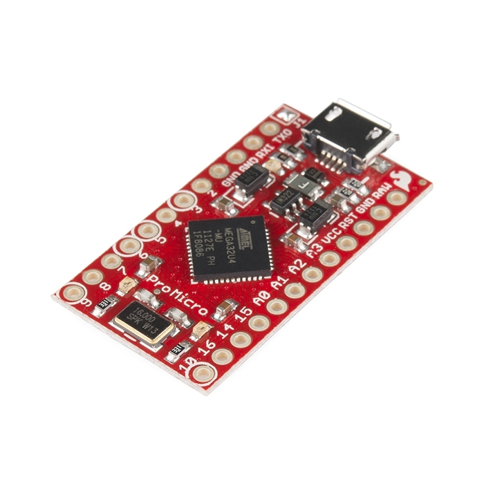
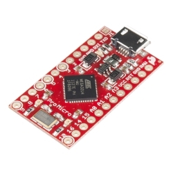
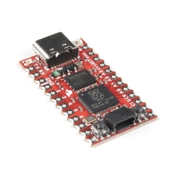
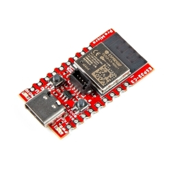
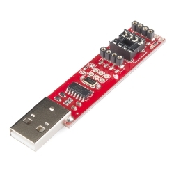
Here at SparkFun, we refuse to leave 'good enough' alone. That's why we're adding to our line-up of Arduino-compatible microcontrollers once more! The Pro Micro is similar to the Pro Mini except with an ATmega32U4 on board. The USB transceiver inside the 32U4 allows us to add USB connectivity on-board and do away with bulky external USB interface.

This tiny little board does all of the neat-o Arduino tricks that you're familiar with: 4 channels of 10-bit ADC, 5 PWM pins, 12 DIOs as well as hardware serial connections Rx and Tx. Running at 16MHz and 5V, this board will remind you a lot of your other favorite Arduino-compatible boards but this little guy can go just about anywhere. There is a voltage regulator on board so it can accept voltage up to 12VDC. If you're supplying unregulated power to the board, be sure to connect to the "RAW" pin on not VCC.

This latest revision corrects the silk error from the last version of the board so that pin 14 is correctly labeled. We've also added a PTC fuse and diode protection to the power circuit and corrected the RX and TX LED circuit.

Not sure which Arduino or Arduino-compatible board is right for you? Check out our Arduino Buying Guide!

Replaces:DEV-10998

  • ATmega32U4 running at 5V/16MHz
  • Supported under Arduino IDE v1.0.1
  • On-Board micro-USB connector for programming
  • 4 x 10-bit ADC pins
  • 12 x Digital I/Os (5 are PWM capable)
  • Rx and Tx Hardware Serial Connections
  • Our Smallest Arduino-Compatible Board Yet!
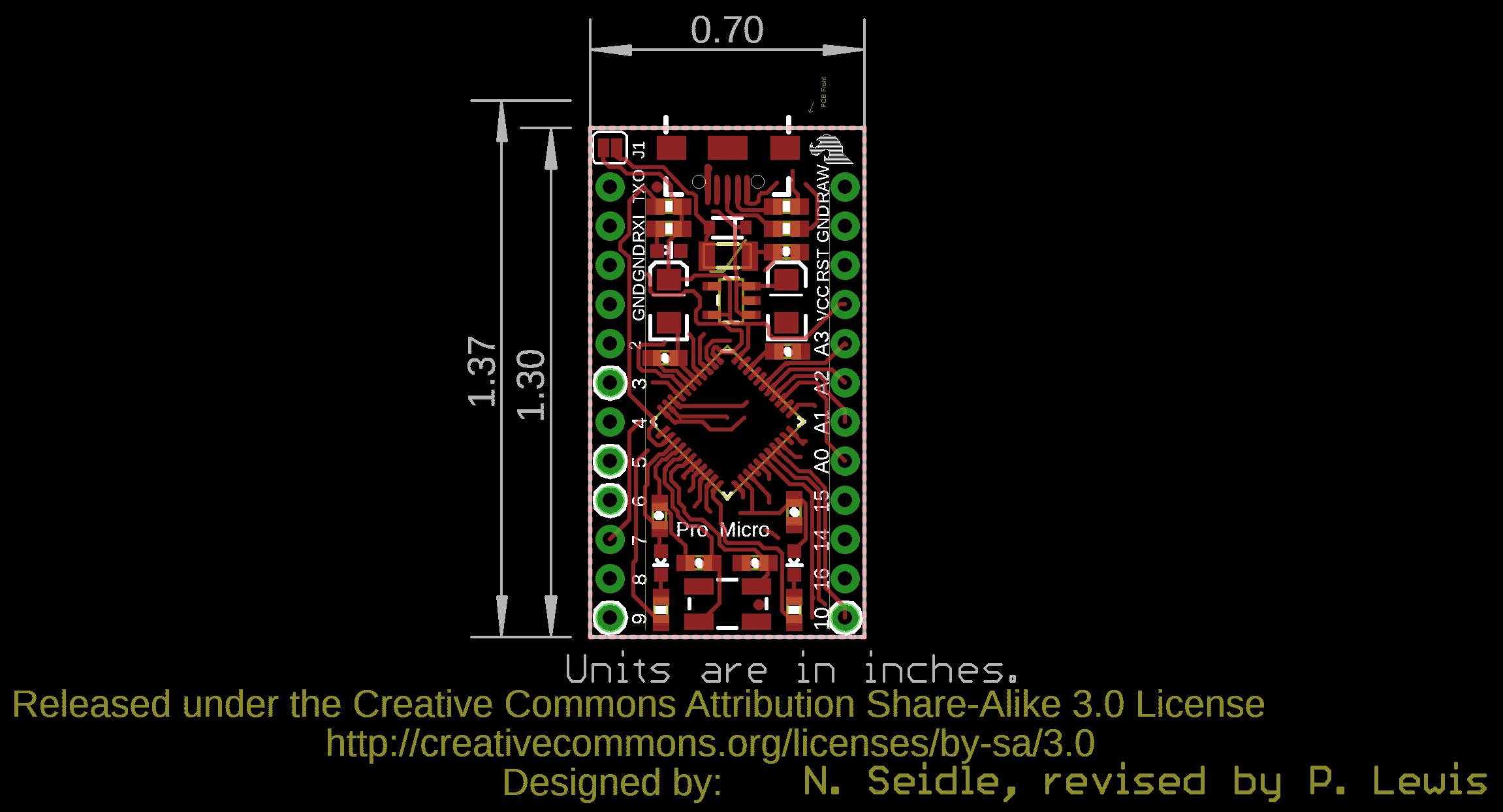
  • 1.3x0.7"

Pro Micro - 5V/16MHz Product Help and Resources

Pro Micro & Fio V3 Hookup Guide

November 8, 2013

An overview of the Atmega32U4-based Pro Micro and FioV3, how to install it, and how to use it with Arduino.

Core Skill: Soldering

This skill defines how difficult the soldering is on a particular product. It might be a couple simple solder joints, or require special reflow tools.

2 Soldering

Skill Level: Rookie - The number of pins increases, and you will have to determine polarity of components and some of the components might be a bit trickier or close together. You might need solder wick or flux.
See all skill levels


Core Skill: Programming

If a board needs code or communicates somehow, you're going to need to know how to program or interface with it. The programming skill is all about communication and code.

2 Programming

Skill Level: Rookie - You will need a better fundamental understand of what code is, and how it works. You will be using beginner-level software and development tools like Arduino. You will be dealing directly with code, but numerous examples and libraries are available. Sensors or shields will communicate with serial or TTL.
See all skill levels


Core Skill: Electrical Prototyping

If it requires power, you need to know how much, what all the pins do, and how to hook it up. You may need to reference datasheets, schematics, and know the ins and outs of electronics.

3 Electrical Prototyping

Skill Level: Competent - You will be required to reference a datasheet or schematic to know how to use a component. Your knowledge of a datasheet will only require basic features like power requirements, pinouts, or communications type. Also, you may need a power supply that?s greater than 12V or more than 1A worth of current.
See all skill levels


Comments

Looking for answers to technical questions?

We welcome your comments and suggestions below. However, if you are looking for solutions to technical questions please see our Technical Assistance page.

  • pu241 / about 12 years ago * / 4

    I got my ProMicro running and it is definitely progress in Arduino evolution! Thanks Sparkfun!

  • Member #8794 / about 12 years ago / 3

    Which are the PWM pins? An analogWrite command on pin 6 doesn't seem to work, even though the schematic seems to indicate it is PWM...?

  • DarK_AlximiK / about 11 years ago / 2

    WTF is that? Binary sketch size: 4,262 bytes (of a 28,672 byte maximum) Found programmer: Id = "BPņ"; type = Software Version = . ; Hardware Version = . avrdude: error: buffered memory access not supported. Maybe it isn't a butterfly/AVR109 but a AVR910 device?

    • Member #498493 / about 10 years ago / 1

      I'm having this problem now. It's really upsetting. I have 2 of these boards and it's happening with both.

  • John / about 11 years ago / 2

    I just bought one, and can't get Serial communication working. I have added this:

    while (!Serial) { ; // wait for serial port to connect. Needed for Leonardo only }

    on the theory that it's like Leonardo, but it didn't fix it. None of the example sketches for Serial work. How can I fix this?

    • John / about 11 years ago / 1

      Aha! Never mind, I solved it. Solution? After uploading the new sketch, you always have to unplug the USB cable, then plug it back in. Then it will run the Serial code in the Setup part of the sketch, that's supposed to print when you open the Serial Monitor. Otherwise, it never will.

      And also, you do need the Leonardo "wait around until I open Serial Monitor" code I posted above, or it can be simplified further as:

      while (!Serial) ;

      Good luck to anyone else pulling their hair out over Serial Silence! I am now very happy with this purchase.

  • geoganoe / about 11 years ago / 2

    I tried using the Pro Micro with the Arduino IDE version 1.0.4, and could not get my sketch to compile correctly. After looking through the IDE source code and the Sparkfun Addon Files, I found that for IDE versions later than 1.0.2, it is best to replace the ~/sketchbook/hardware/SF32u4_boards-master/cores folder with a symbolic link to the real arduino cores folder. On my Debian Linux system that is at

         /usr/share/arduino/hardware/arduino/cores
    

    After making that change, my sketch built correctly, and worked just as it had on the Arduino Uno where it has been used in the past.

    It appears that some of the changes for IDE version 1.0.2 made the IDE cores folder compatible with the Sparkfun version. After version 1.0.2, other changes in the IDE have made the Sparkfun version incompatible with the rest of the Arduino IDE.

    Has any one else had problems getting the Pro Micro to work with IDE version 1.0.3, 1.0.4, or 1.0.5?

    • geoganoe / about 11 years ago / 1

      After playing around with the Sparkfun Addon files a little more, I think I have found a better solution than using the symbolic link. If I edit the ~/sketchbook/hardware/SF32u4_boards-master/boards.txt file to replace the line:

       promicro16.build.core=arduino
      

      with the line:

       promicro16.build.core=arduino:arduino
      

      then the build will use the default Arduino IDE cores folder instead of the one from Sparkfun. The advantage of this approach is that it is no longer required for the user to know where the default IDE cores folder is located, and if it changes this change will hopefully automatically find the new location. Also, this method will likely work under Windows as well as Linux.

      I suspect that the other board types should be changed as well, i. e.:

       promicro8.build.core=arduino
      

      to: promicro8.build.core=arduino:arduino

      etc.

      • Nachos grande / about 11 years ago * / 1

        I tried your solution but still cannot manage to upload using 1.0.3. It just keeps saying it cannot find leonardo on selected port when i have sparkfun pro micro 5v/16 Mhz selected. Im using the provided addon files

  • Member #428979 / about 11 years ago / 2

    My $0.02:

    I couldn't get the nano to work correctly with my PC for my life. I must have sat there for 6 hours over a few days trying different drivers, reloading the bootloader, etc. I plugged this guy in, worked first try.

    A lot of people here have complained about the microUSB breaking off, but I haven't had that happen with mine yet over the course of a few weeks. Others may have just gotten a bad batch.

    Take note of the upgraded firmware, it saved my ass more than once. I was trying to use timer interrupts and learned the hard way that the ATmega16U2 timers are different than the 32u4. I uploaded a timer interrupt example using timer2, and it became unresponsive (TX LED stuck on). I ended up having to use the double tap reset, load a blank sketch onto it, then reload another program to get it out of "brick"state. If anybody else has this issue:

    1. Connect the Pro Micro to your PC. Sometimes I would get a "USB not functioning properly" and others it would show up as a COM port.
    2. Double tap reset. When it's connected as a COM port in bootloader mode, select that COM port in the Arduino IDR.
    3. Write a blank sketch, hit upload, then immediately double tap reset. You should see the TX and RX LEDs blink, and you'll get an error saying something along the lines of "COM port already in use". Disconnect the board and close the IDR. Now you should be able to upload code again.

  • Member #148096 / about 11 years ago / 2

    There are a few things that need to be updated on the info to avoid unnecessary trouble.

    1. This board (current version) comes with Caterina bootloader, instead of Diskloader (as described in the Arduino Buying Guide page). Please update to correct that.

    2. The Caterina bootloader is modified so that it does NOT enter bootloader mode unless you reset twice in short interval. This is specified in the "Firmware Note". But it is not mentioned at all in the "Getting Started Tutorial". As a result, uploading from Arduino IDE would not work directly.

    Because there is no reset button on this board, to load user code onto this board (with Arduino IDE / AvrDude), you will need to short RESET pin to GND pin with a wire twice in short interval (right before or after you pressed upload in Arduino IDE or started AvrDude). This will bring the board to bootloader mode in order to receive the uploaded user code.

    • M-Short / about 11 years ago / 1

      We are working on a lot of new tutorials hopefully including a new tutorial for this. With the bootloader it does run the bootloader, just not for the full 8 seconds. The bootloader is what is actually looking for the double-tap. But you should have no problem uploading code to the board from the Arduino IDE (including having to manually reset the board). If you are having problems uploading code please email us at techsupport@sparkfun.com

      • Member #148096 / about 11 years ago / 1

        I had problem uploading code to my Pro Micro from Arduino IDE ... until I figured out the double tap dance. Is there some other way to make it work (other than the double reset)?

  • BobNKnob / about 11 years ago * / 2

    Via JAVA how do I get the the shorted pin say 9 to ground? Thanks. Library found here http://code.google.com/p/java-simple-serial-connector/

    import jssc.SerialPort; import jssc.SerialPortException;

    public class Main {

    public static void main(String[] args) {
        SerialPort serialPort = new SerialPort("COM1");
        try {
            serialPort.openPort();//Open serial port
            serialPort.setParams(9600, 8, 1, 0);//Set params.
            byte[] buffer = serialPort.readBytes(10);//Read 10 bytes from serial port
            serialPort.closePort();//Close serial port
        }
        catch (SerialPortException ex) {
            System.out.println(ex);
        }
    }
    

    }

  • edanv / about 12 years ago / 2

    Since this is a virtual COM port over USB, how can we control the baud rate ? it seems I can set any value in Serial.begin, and also any value in the DCB on my windows PC, I still recieve characters (even if the speeds don't match). And it consistently takes 30 ms to get 9 characters (timing the call to ReadFile(,,9,) on the PC ). The specs of the 32U4 speak of 2 megabit/s ?

  • Member #32850 / about 12 years ago / 2

    I have uploaded test code that should put the chip to sleep, waking up periodically to take a sensor reading. Unfortunately in going to sleep, the USB drops off and the PC can't see the COM port any more.

    Any suggestions as to how I can prevent the code from running on power up, or some sort of ICSP alternative? (so I can upload new code)

  • JoyMonkey / about 12 years ago / 2

    So with the beefy regulator and diode and fuse in place, if I was to accidentally feed something over 16v into this (let's say 24v) would it just shutdown, or would magic smoke come out?

    • JoyMonkey / about 12 years ago / 2

      A big puff of smoke from the regulator and one of its caps just answered my question. :( As is my unfortunate way, I accidentally sent 16.8V to RAW. The Pro Micro does still work perfectly if I feed a nice safe 5V into VCC, but its own regulator ist kaput!

    • mvadu / about 12 years ago / 1

      Regulator datasheet: http://www.micrel.com/_PDF/mic5219.pdf Absolute Maximum Ratings(1) Supply Input Voltage (VIN)..................–20V to +20V

      The way the regulator is setup in 5V board makes the input raw voltage to be applied to both input and output of the regulator, and thus above 12V the regulator just dies.

  • KerwinLumpkins / about 12 years ago * / 2

    USB connector is fragile. I reprogrammed my pro micro about 10 times and then the USB connector broke off the board, taking some traces with it. Otherwise, I'm pretty happy with the board. I'll have to figure out some way to get another connector on it. I followed the user guide for setup on a Windows 7 64 bit machine and it went just as advertised. This board is much faster to program than an Uno board that I have. On my windows 7 64 bit machine, the uno takes easily 60 seconds to connect and program. The pro micro does it in 15.

    • aaronbear / about 12 years ago / 3

      I agree about the fragile USB connector on these boards, I only got four or five plug/unplugs before mine snapped right off. I was pretty disappointed, I really dislike the whole micro USB connector in general and wish SparkFun wasn't using them so much in their new products.

    • Kevin Vermeer / about 12 years ago / 2

      A bit of superglue does wonders on these connectors; solder and SMD pads really aren't designed to take any repeated stresses. Solder is very brittle and will develop stress fractures easily.

      This isn't a problem if this was mounted in an enclosure where the surrounding plastic could stabilize the connector (that's what the wings on the end of the connector are for), but it's not so you have to use superglue.

      Sparkfun, if you're listening, this would be a great place to use the glue attachment for your pick-and-place machine. Your pick-and-place does have a glue option, right? If not, consider contracting this one out to a manufacturer that can do it.

      • Jay Pee / about 11 years ago / 1

        Yeah great. I did the superglue thing. Now I have a usb cable superglued to my board. MmHmm. Superglue. Awesome.

      • KerwinLumpkins / about 12 years ago / 1

        I built up a new board using a new pro micro using superglue and the problem still develops fairly quickly. the connector just isn't up to handling stress force. I do have this in an enclosure which helps but it still happens. Using pro micro was a prototype solution only. long term I will design my own board and i definitely WILL NOT use a SM only connector. i plan to use a mini B through hole to avoid this problem.

        Just a warning to those buying these boards. That connector will likely break on you if you connect and reconnect a cable more than about 20 times.

        • MarkFromNJ / about 12 years ago / 2

          Pull too hard, break connector. Don't pull hard, connector lasts for months like mine. Physics is a bit*h

        • this is not true. I have many of our boards with micro-usb connectors on them and I use them daily and have never broken a connector. these are not panel-mount connectors, so using them through a case is not ideal. if you need to do so, use sugru or something to attach it to the case as strain relief. if you are forcing a cable in and out of it without holding the connector to secure it, yes, it will break because this is not intended use.

          • KerwinLumpkins / about 12 years ago / 3

            I swear I'm not lying. I hold them with my fingers as I insert and remove cable. 2 other users of the thing I made with them have this problem, so it doesn't appear to be my clumsiness. I need something reliable and robust in the field with many users, so it's not for me. Mechanical is my only complaint. The board functions great and is electrically very solid.

          • tyggerjai / about 12 years ago / 2

            Just saying, as someone who bought a ProMicro and has the same problem, this is a really disappointing response. If I buy something from a company with whom I have had good experiences before (as I have with SparkFun), and the product has an issue, I'll chalk it up to a bad batch, or a one-off design problem, and keep spending money there. If the company response is not far short of calling customers liars and refusing to acknowledge the problem, then I won't.

            • I apologize, I'm not trying to call anyone a liar at all! Like Aaron said below, if they aren't properly reflowed, there can be problems. I just don't want to give the impression that the connectors themselves are fragile and flawed.

              Do you still have an issue with a board?

              • tyggerjai / about 12 years ago / 1

                The reflow hint was great - I resoldered both sides of the connector, tweaked it into a position with good contact, and now it seems ok. I might add some superglue, but like I say, it has a dedicated cable now, so there should be very little stress on the connector. And yeah, clearly it's not like you can step up to a more robust connector without compromising the size and utility of the board - now that I've resoldered it feels fine.

                Cheers!

            • Sorry about that. Sometimes the connectors don't flow well and they become abnormally fragile. Contact techsupport@sparkfun.com and they will help you. Sorry for the confusion.

              • tyggerjai / about 12 years ago / 1

                2 minutes with a soldering iron seems to have fixed it - had to tweak it back into a position with good contact, but it feels happy now - thanks for the reflow tip. Back to being loyal SparkFun customer, albeit through LittleBird these days.

          • Member #131879 / about 12 years ago / 1

            I noticed my USB connector was moving slightly when I removed my cable from the board. When I took a close look at the part, it is obvious the front two tabs of the USB connector received a cold solder joint. I can lift the part from the solder pads with my fingers.

            • Hi, please contact us in techsupport@sparkfun.com (if you can provide your order number too, that would be great) and we can help you! Sorry for any inconvenience!

          • Heshamo / about 12 years ago / 1

            I have got 4 Pro Micro boards and one of them had a VERY weak USB connector (3.3V one) The rest are fine. Can I return it and get another one?

    • Member #228962 / about 12 years ago / 1

      Thanks for the reminder. I don't have this board yet, but other boards with this connector have broken the same way. USB micro is fragile. The best way to deal with the problem is with an enclosure designed to exact tolerances. I've done this at Ponoko, have some enclosures for sale, and have been perfecting the process. Maybe I'll design one for this board when some arrive. I use a 6" dongle-style mating adapter for a pricey development board with the same risk - but these adapters are uncommon. The mating adapters for sale at Amazon or NewEgg look like good solutions for this problem. They have something to hold onto and are cheap enough to buy a few for semi-permanent attachment to prototyping gems. Search Amazon for "USB Micro Adapter".

    • philfromseattle / about 12 years ago / 1

      Looking at the pictures of this board and other similar format 'duinim, it looks to me that there is more of the connector hanging off the edge of the board. This pushes the case tab's solder pad right to the PCB edge and thus increases the amount of flex on the pads. The teensy's connector's tabs are at least 100 mils from the edge.

  • So when can we expect a Pro Micro++?

  • Ben121 / about 12 years ago / 2

    The real USB line of Arduino-like boards was pioneered under the name Teensy,not Leonardo which is a knock off of Teensy by the Arduino team - which have been peddling serial ports in a USB world for way too long. This board supports RealUSB - which offers concepts like self-identification (no com port pull-down), baud rate negotiation (No Baud rate errors), and can avoid vcomm drivers (no BSOD crashing) This board brings the possibility of respectable product development - a world foreign and unreachable by anything the Arduino team have to offer. - as a bonus, the pins are aligned on .1 centers - always a concept.

    • Zmaster / about 12 years ago / 1

      I agree with most of your considerations. I'd like to avoid vcom too, do you know some other easy way to make a pc software communicate with this? Actually, i'm fine with serial streams, what i hate are the com port numbers. I was happy with FTDIs because using their libs you could open the communication using the device name instead of the com port number.

  • AdrianFreed / about 12 years ago / 2

    To save money, get more ADC�s and all the features of the 32u4 boards you will want to look at the teensy and adafruit�s 32u4 board. Adafruit just announced the Flora etextile platform based on the 32u4. There are also now 32u4 boards from Olimex and others...

  • philfromseattle / about 12 years ago / 2

    OK, I'm confused - what happened to dev 10998? I think it lasted about a femtosecond. Is this just a rev of the PCB?

    • jimblom / about 12 years ago * / 2

      Yup, this is mostly just a PCB rev. Silk errors were fixed, the RX/TX LEDs are now pulled up to VCC. There are a few other schematic changes including the addition of a 500mA PTC, and some reverse current flow protection. We've also got a beefier, 500mA LDO regulator on there now.

      If you want to compare schematics: v10 (old) to v11 (this version).

      • ghjeng / about 12 years ago / 2

        “SoftwareSerial” library doesn’t compile… any ideas?

  • Member #498493 / about 10 years ago / 1

    Pulled out two of my Pro Micros after not using them for a couple of months. Now I get the following errors: Binary sketch size: 6,226 bytes (of a 28,672 byte maximum) Found programmer: Id = "BS"; type = Software Version = . avrdude: error: buffered memory access not supported. Maybe it isn't a butterfly/AVR109 but a AVR910 device?

    What appears to be happening is that, after pressing program and double resetting the micro, it looks like the micro enters the bootloader, starts to get programmed, but resets before it's done. So from the device manager I see the com port change, the micro tx/rx LEDs start blinking, then the com port changes back to the normal port before the programming is done. Then the above error shows up.

  • Member #507443 / about 10 years ago / 1

    I need to use Freqmeasure on the Pro-Micro. On the UNO R3, the input has to be on pin 8. Does one of you know if there's a similar restriction on the Pro-Micro and, if so, which pinis used? Thanks for the help in advance.

    • Kamiquasi / about 10 years ago / 1

      There's probably a similar restriction, as the library seems to use pin 8 specifically because of its ICP (input capture) facility. The chip used on the Pro Micro is slightly different, so you can't use the same pin number. The datasheet for the ATMega32U4 does note that there are two pins that can be used as an ICP - PD4 (ICP1) and PC7 (ICP3 - no, there's no ICP2). Both are 16 bit, but PD4 seems to require less tweaks (its description is pretty much the same as that on the ATMega328 used on the Uno) and you might be able to use that directly after modifying the library. The physical pin on the Pro Micro board's edge is pin 6. Good luck!

  • Member #474618 / about 10 years ago / 1

    How come no more will be made?

    • We've revised it. We'll still be making it, but there are a few changes so it will be under a different part number.

      • qwertymodo / about 10 years ago / 1

        Please tell me the changes include this pinout fix: https://forum.sparkfun.com/viewtopic.php?f=14&t=37096&p=165977

        Mine is on its last legs after the USB port ripped off, and my repair job has slowly developed intermittent drop-outs, so I'm going to be in the market for a new one...

        • It doesn't look like that design has changed the reset pin between RXI and GND. However, I think this may have something to do with the different bootloading process on the Pro Micro, regarding why they originally went with this format.

          • qwertymodo / about 10 years ago / 1

            That's unfortunate. I don't see how the bootloader would have any affect on the board pinout decision...

  • alruf / about 10 years ago * / 1

    I can't say I am too pleased with the Sparkfun Pro Micro given the outdated information made available for its use and overall difficulty (compared to Arduino Uno and Mega) to get it to run. The first struggle was to find where MS hid the option to disable the signed driver requirement on Windows 8.1 64bit (the SF guide refers to old versions of Windows where it was easier to override the requirement. The geniuses at MS made it way more convoluted to switch it off). Once I found the instructions I was finally able to install the driver but hit the next hurdle right away. Any time I select the Sparkfun Pro Micro 5V / 16MHz I am unable to compile anything as the compile errors out. My guess is that the add-on files are not compatible with Arduino IDE 1.5.5 given I installed version 1.0.5 on a separate VM and was able to compile without issues. I can't use the VM to upload to the Pro Micro because each time the device gets re-enumerated the VM drops the connection to it and I just can't re-enable it fast enough having to reset the board twice and re-select it in the IDE. Also, I found a couple features/fixes between 1.0.5 and 1.5.5 that I need/want so I'd rather not attempt a downgrade risking breaking my other sketches and/or compatibility with my system... (I am not getting into the struggle I went through to get the MP3 player shield to work on my UNO for similar lack of info reasons). Long story short, it would be nice if Sparkfun revisited the original guide to add all the tidbits of info otherwise scattered elsewhere to make it easier to use their hardware on up-to-date systems (newer revisions of Sparkfun hardware, latest OS version, latest IDE even if considered beta - especially when it appears Arduino keeps the IDE in beta for extremely long insane periods (1.5 beta started in Oct 2012 and still is!!). I am a new Arduino user and Sparkfun customer and am loving it but I see some room for improvement here to reduce the annoying and unnecessary frustration :) I guess I will have to set this aside until fully supported... hopefully soon. End of rant :-)

  • Member #466344 / about 10 years ago / 1

    Bought this board and i want to supply it with a 9 volt battery. At which pin should i connect it in order not to cause any damage? RAW and GND or Vcc and GND?

  • JSteiner / about 10 years ago / 1

    I am completely unable to install the driver for this board. I've used them in the past on other machines, but my 64-bit Win7 machine just says driver not found, even with the most recent drivers on the page. Anyone else had this issue?

    • l0gikG8 / about 10 years ago / 1

      Mine is running on 64-bit Win7. Be sure to browse to and select the unzipped ProMicro-Driver-190612 folder when you do the update driver step from the tutorial

  • Member #487344 / about 10 years ago / 1

    I can't use the Arduino IDE (complicated reasons) - so I use Makefiles, g++ and avrdude directly from Ubuntu Linux.

    I have two Pro-micro boards and a Leonardo. I did the development work on the Leonardo - then decided to shrink the design onto a Pro-micro. Since I'll eventually be making around a thousand of these things - I need to evaluate the switch over to using the Pro-Micro rather carefully. To that end, I bought an "official" (5v/16MHz) SparkFun Pro-Micro and a 5v/16MHz clone from someplace in China (it's labelled "Deek-Robot"). The two boards look identical in every way, except for the PCB color and the name on the back.

    The Deek-Robot board works perfectly as a Leonardo - same exact software, same avrdude settings...which I presume is because it uses the exact same original CATERIN bootloader as the Leonardo.

    But I can't get the Sparkfun board to talk to me. I presume that's because of the modified bootloader...but double-resetting it doesn't work - I can't figure any way to get it to work with avrdude.

    What I need is either:

    (a) A way to re-flash the bootloader back to the original CATERIN using avrdude....or... (b) The correct settings for avrdude to send sketches to the modified CATERIN bootloader.

  • KirAsh4 / about 11 years ago * / 1

    As others have pointed out, the USB connector on these boards is very fragile. I just got mine a few days ago. I soldered headers on it tonight, plugged it in, used it for a bit, then tried removing the USB cable and noticed the connector moving a bit. After a few more times of plugging/unplugging (uploading sketch changes, then running off of batteries), the connector completely came off taking the traces with it. So now I have a board I can no longer use with a USB cable. That's $20 wasted and a dead project now.

    Personally I would not use these connectors, and if SFE insists on using them, at least find some that have guide pins that fit into holes in the PCB (like a genuine Arduino Leonardo has), or those with 4 solder tabs, not just two. Just having the traces and two edge pads cope with the stresses of plugging and unplugging a USB cable is just plain dumb, they will break. And Robert C., I'm sorry, but you telling us that you have several boards with this connector and never broken one does not make it any more okay against the several folks on here that said theirs broke. I do appreciate what you're saying, however like others, I too was holding the connector/board before plugging or unplugging the cable. This needs to be revisited and possibly changed for a better connector. You can't expect everyone to know that they need to be holding it every time.

    As I said, unfortunately, because I now have headers soldered to this board, I highly doubt SFE will exchange it for a new one so I just wasted $20 as I can no longer use it as originally intended, WITH the USB connector. I have no choice now but to go find something elsewhere to use. I simply can't justify spending another $20 for a new board knowing that the connector will likely break off again. Sorry but this is a product I can not recommend to others.

  • DarK_AlximiK / about 11 years ago / 1

    Binary sketch size: 4,864 bytes (of a 28,672 byte maximum)

    avrdude: ser_send(): write error: sorry no info avail

  • goseese / about 11 years ago / 1

    I am having a problem getting this board to work with Mac OSX. I can not get the tty.USBXXX to show up as a USB modem.

    I have the correct proMini 5V/16MGHZ board selected, but the serial port menu never shows any USB serial ports, only the blue tooth options.

    I have installed the latest correct FTDI drivers for my mac. I even contacted tech support at ftdichip.com and asked them for sure which drivers are the correct ones for my Mac.

    This is my first attempt with an Arduino, so I can't say if any other Arduino boards would ever work.

    However, googling seems to report many people with the same problem (No tty.USBXXX when Arduino board is plugged in ) and no fixes.

    Does anybody have any suggestions?

    If I go to my About this Mac => System Info => USB no devices show up there either aside from my standard in stalled items.

    I have tried different USB ports and different USB cables. This is a cable I also use to tether my phone so I know the cable works.

    I do also have a Teensy 3.0 that I purchased at the same time. Went through all the install steps there and am having a similar problem. No tty.USB shows up in Arduino app.

    I have a second Mac here on 10.7.5, Exact same results on that mac as well.

  • John / about 11 years ago / 1

    I just bought one and can't get Serial to work properly. I have put in the:

    while (!Serial) { ; // wait for serial port to connect. Needed for Leonardo only }

    ...but it doesn't fix it. None of the example sketches for Serial work. How can I fix this?

  • NickMortimer / about 11 years ago / 1

    Had lots of problems getting this board to work

    1. Windows 7 64 kept saying sparkfun usbtoseial not pro micro. than to force it to install.

    2. Cannot upload to it uploading fail with Binary sketch size: 6,184 bytes (of a 28,672 byte maximum) Found programmer: Id = "B»["; type = Software Version = avrdude: error: buffered memory access not supported. Maybe it isn't a butterfly/AVR109 but a AVR910 device?

    can't seem to get past this point have set the board correctly

    any help?

    • John / about 11 years ago / 1

      Well, I just got it working, also on Win7 64bit. You have to install the correct driver, and then put stuff in the "Arduino/hardware" directory. Just follow the instructions in the Getting Started Tutorial above.

      Do you have SparkFun Pro Micro 5V/16Mhz as an option in your boards menu, and is it selected?

  • Member #474520 / about 11 years ago / 1

    This board does not work under the beta Arduino 1.5.4. I spent a lot of time getting it to work and it does not. Buyer beware that it is only operational under the relased IDEv1.0.1, that's why it states this in the feature list.

  • Member #455836 / about 11 years ago / 1

    Hi, I need help please. I try to install the Arduiono Leonardo bootloader on my pro micro with a second pro micro as arduino-as-isp but I always get the error: avrdude: stk500_getsync(): not in sync: resp=0x00 What do I do wrong?

  • thibalte / about 11 years ago / 1

    Major point of failure on the micro usb connector.. ripped it clean off 5 minutes before a show while calibrating, not funny. The strength required to unplug a cable seems to be larger than what the soldering can handle.. Otherwise it's awesome, but I'd recommend to hotglue the sides of the connector otherwise you're in for a bad surpise at anytime.. maybe guys can do something about it, I could only use both less than 5 times before it broke off, and I was very careful! :(

    • We are actually working on finding stronger connectors for these boards currently. Sorry to hear you had such a rough go with yours! Try contacting techsupport@sparkfun and they may be able to help you.

  • Member #466812 / about 11 years ago * / 1

    Edit: Nevermind. After reading more about the problem with powering from car batteries (that are installed in machines which are running) I will definitely go with the USB charger. The L7812CV is not enough alone.

    Original post: I have bought this one and getting ready for a project. It will be mounted on a tractor lawn mower. Since the alternator puts the voltage up a bit (haven't measured yet but I guess on 14 volt) I need take it down a bit. Just happened to pick up a ST Microelectronics L7812CV voltage regulator. Datasheet here (view page 7): http://pdf.datasheetcatalog.com/datasheet/stmicroelectronics/2143.pdf Assuming the voltage is 14.5 volt or above, should I use this or will I be far better off ripping a no-name USB charger for car lighter socket so I get 5 volt? If using the L7812 is fine, should I use VCC or RAW?

  • vvvjv / about 11 years ago / 1

    I'm trying to get the IRremote library (see http://www.righto.com/2009/08/multi-protocol-infrared-remote-library.html ) running on the 5V/16MHz Pro Micro. The IRremote code has a lot of #if ... #elif ... #elif ... #elif ... preprocessor directives for various boards, but this board is not one of the choices. Is the Pro Micro equivalent to, say, one of the Teensy boards so far as timers and interrupts are concerned?

    • Member #757640 / about 8 years ago / 1

      open IremoteINT.H and search for line : "error "Please add OC3A pin number here\n"" and replace it with " define TIMER_PWM_PIN 5 "

      and it will work fine.

    • vvvjv / about 11 years ago / 1

      After a large amount of trial and error, I managed to get things to work by forcing IRremote to use timer 3 and PWM pin 5.

      • Member #731007 / about 8 years ago / 1

        Could you provide more information on how you did that? I think I'm running into the same problem.

  • Member #458576 / about 11 years ago / 1

    I got it and can program it according this tutorial. But it is once. After it, My PC(Win7-32bit) says "unknown device". Please help me.

  • Member #427137 / about 11 years ago / 1

    Can this be switch to 3.3v? the jumper on the board is for switching the voltage reg output. closed for 5v, open for 3.3v... any ideas?

  • Member #450830 / about 11 years ago / 1

    Dose any body happen to know if the Timer1 library works with the pro micro. library can be found at: http://code.google.com/p/arduino-timerone/ . I would just test it, but my board has not arrived yet. If nobody responds, ill update this after I run some tests and let others know of my findings.

    • Member #619901 / about 8 years ago / 1

      Member #450830 were you able to use timer interrupts with Pro Micro 16MHz board ? If so would you be able to share that example with me ?

  • tzq33tdq / about 11 years ago / 1

    Can I use I2C to connect to https://www.sparkfun.com/products/99 RTC module?

  • Member #428979 / about 11 years ago / 1

    I found a reliable solution to using interrupts with the micro. For others that aren't programmers (like myself), see my forum thread below:

    https://forum.sparkfun.com/viewtopic.php?f=32&t=35847&p=160331#p160331

    I used C code to get the job done, but it works. This should enable access to all 5 the external interrupts. Chapter 11 of the datasheet was also very helpful, although didn't have any examples. I didn't explore it any further, but there is also 8 pin change interrupts available on the chip through C code.

  • Member #380046 / about 11 years ago / 1

    Dear SparkFun, compared to a regular Arduino you left out Pin 11, thus disabling one of the output compare pins for the 8 bit PWM. Since my project uses both 8bit PWM output compare registers this is disappointing. I should have looked at the schematics before buying!

    • Member #749529 / about 8 years ago / 1

      I have the same problem - why would they leave out one of the more useful digital pins? I bought this board for the sole purpose of thinking it had the 4 output compare pins of the 32U4 (i needed all 4) but 1 is missing. Waste of $20. I found an alternative at Adafruit though - it also has 5v logic + a 5v pin (not sure mA rating though - its 500mA on this one) and all pins broken out - https://www.adafruit.com/product/1086

      • CF / about 8 years ago / 1

        Is it Atmega32U4 pin PB3 you're looking for? Arduino calls that pin 11, but on our board we've redefined it to pin 14 in software. Anywhere you would normally call pin 11, just rename it to pin 14 and you should be OK. If you're using SPI, it's MISO either way. I don't recall at the moment why we renamed that pin, but we did have a good reason for it.

    • MikeGrusin / about 11 years ago / 1

      Very sorry about that, almost all Arduino boards sacrifice one or more MPU pins to save space and stick to the standard set of I/O. You might consider the 32U4 Breakout board, that does break out all the pins for those who need them (like you), including B7.

  • AeroGuy_123 / about 11 years ago / 1

    Does anyone know what diode the board is using? A link to a supplier would be very appreciated!

  • Member #413543 / about 11 years ago / 1

    Does it have 5v power out? If I like to connect something more?

  • Member #413543 / about 11 years ago / 1

    ok I did buy it and it work great. But the problem is that I did not think about before I buy this that I need PC7 Is that any way to fix that?

    I was going to send IR with a nice Remote Library but they use PIN 13 for send IR and this does not have that.

  • Member #417012 / about 11 years ago / 1

    Can the LEDs be disabled? Is it ok to just snip them off with a pair of pliers?

    • Kamiquasi / about 11 years ago / 1

      The red one is tied to the voltage regulator, you'd have to 'snip' that off (desoldering, or putting some tape over if the light's bothering you, would be much cleaner). The green and the yellow are on pins of the microcontroller - whatever program is running on it is what controls those two, adjusting the programming should be an option there. They don't seem to go anywhere (well, to VCC), so probably also OK to remove entirely if you really wanted.

  • qwertymodo / about 11 years ago / 1

    One really big problem I have with this board was the decision for pin 3 (or 2, depending on how you number them, I mean the pin right next to RxI) to be GND instead of RST. This is not consistent with the Pro Mini, and breaks compatibility with the Mini USB Host Shield from Circuits@Home. It's taken me the last 2 hours of emailing the Circuits@Home tech support to figure this out. Why did you feel the need to change the pinout? I don't see any real benefit from that change, and I'm disappointed that it breaks the USB Host Shield.

  • Member #400485 / about 11 years ago / 1

    Bought two of these recently. Cannot upload to either one. It hops com ports like a frog, and just will not accept uploading.

    An older one works outstanding.

    I need a clue, please

    • Member #414233 / about 11 years ago / 1

      I also bought a Pro Micro 5V/16MHz recently and am having the same problem on Windows 7. I was able to upload example code once but the board will no longer take new code. I have tired the double tap reset but that is not working. When I attempt the reset, the board hops com ports. Also when the board is connected over USB the TX light (closest to pin 7) stays lit. Any suggestions or help would be greatly appreciated. Thanks!

      • Member #400485 / about 11 years ago / 1

        The ProMicro add - on above for the SF32u4 boards above contains the correct drivers that need to be installed. I FINALLY got my two new ones to work correctly. Uninstall the Leonardo drivers, stop the new driver installation, till you can manually point to the drivers file in hardware|SF32u4_boards|drivers folder. Ensure the SF32u4 folder is also only one deep in the hardware folder. If the SF32u4 folder only contains another SF32u4 folder, the IDE cannot see what is in there

        If you have ANY files from an older ProMicro in the Ardruino IDE, you may want to edit the SF32u4 boards.txt file with the word "new" in front of the board name, because the OLDER board name and the NEWER board name are so similar, you cannot make out which is which. The difference in board names comes down to how the voltage/Hz is listed, as in "5V/16Hz" and "16Hz/5V"

        The double tap thing should not be needed, and yes the board will hop com ports when you do that.

        It was explained to me like this: "ATMega32U4 boards are a bit odd. The actually are running 2 pieces of code. The first is the bootloader and the second is your sketch. Each if these pieces of code has their own VID/PID (vendor ID/ part ID) numbers which is what the computer uses to recognize USB devices. When you first plug in the boards you should see one COM port show up, after a second or two it disappears and a second COM port shows up. This is for the bootloader and the sketch. When you go to upload new code you basically reset the device causing the board to enter the bootloader stage, and the code is updated. The Caterina bootloader that Arduino uses by default has the bootloader running for 8 seconds before switching over to the sketch every time! We modified the bootloader so that its only a second or two, but added the double-tap feature in case you needed to get into the bootloader for longer. You shouldn't have to use this to upload code normally though."

        Michelle in Tech support and I had a fairly long series of emails go by making my boards work, and all the above info is mostly what distilled out of it.

  • Member #397985 / about 11 years ago / 1

    I bought this as part of my Sprinkler controller system, which can be controlled by a freebsd server.

    Unfortunately FreeBSD does not assign a /dev/ttycuaU* port for this device. FreeBSD only recognise the Pro Micro as a mouse (usm0).

    Dissapointed.

  • edanv / about 11 years ago / 1

    I have so far destroyed 3 of those by ripping out the USB connector. Would it be possible to have a new revision that uses the micro usb connector with thru-hole tabs (a la raspberri pi). Thanks.

  • Member #137553 / about 11 years ago / 1

    Well, I broke my second connector. The first was because I used it as leverage taking it off the breadboard. Doh! The second was a spectacular backflip when the USB cable wrapped around my leg to get up. Not a design problem. BUT, I now have two bricked Pro Micros. Is there a way to rescue these guys? I can't see any traces left (all plastic) to be able to solder to. I've seen how to program the Pro Mini's via another Arduino, but I can't seem to get this work on the Pro Micro. Is there a different trick with these guys?

    • BobNKnob / about 11 years ago / 1

      You could get a USBtoTTL and connect the RX TX POWER GND on the PRO MICRO I think.

  • engineer77 / about 11 years ago / 1

    5 pins that appear to be perfectly good are labeled "not used" in the schematic. Why is this?

  • Member #278912 / about 11 years ago / 1

    Is it possible to use I2C with this board?

  • tom jennings / about 12 years ago * / 1

    (updated) huge hassle with Win7 and Win8. Both have same issue. I do not get the "installing new hardware" popup -- i must have missed/ignored it and it only pops up once. In Device Manager, when the Pro Micro is plugged in, it shows up as Other Devices/Arduino Leonardo with yellow \!/, Properties says 'no driver'. Nothing can be done to uninstall or delete it.

    Did this on two machines; on the Win7 machine i restored settings (registry, etc) back to yesterday (before hardware plugged in).

    Manual "scan for hardware changes" does nothing (since it thinks it has Leonardo). Update driver for that device, browse local folder for the Pro Micro .inf file, "no driver found".

    Uno and Diecemila still work normally.

    ALl of the above happen without the IDE invoked of course. It's a system problem.

    I can interpolate around the outdated tutorial (it's for XP) but the fundamental problem is that it thinks it already has a driver for that ID.

    Any suggestions?

    • tom jennings / about 12 years ago / 1

      I'm still stumped. There seems to be no way to get windows to recognize this board as Pro Micro and dislodge the disfunctional "Leonardo" business. Nothing here, nothing in the docs. Tried deleting USB associations from the registry, broke things trying.

      Its entirely likely that on my first attempt i got the install process wrong (interpolating as i was from your Win XP example. M'soft has released two major OSs since XP; drivers should reflect that.

      I realize this is is likely my own doing for installing it wrong. But there seems to be no way out of an entirely reasonable mistake.

      So basically I appear to have no choice but to ditch the Pro Micro as a $25 loss, and go with the Pro Mini and known-working FTDI adapter.

    • tom jennings / about 12 years ago / 1

      no joy. no idea why the Pro Micro always appears as 'leonardo' with no driver.

      in win8, right-clicked the pro micro .inf, selected Install, it complained about it being unsigned. Alas, got it to ignore that and install anyway (http://answers.microsoft.com/en-us/windows/forum/windows_cp-hardware/how-to-install-unsigned-driver-on-windows-8/fd19f3b1-ac35-4aa0-84c0-58b66b382d43). No change; still thinks i have a leonardo plugged in/no driver loads.

      I've only cursorily read about the unusual Leonardo driver situation, tbh it's scaring me off this one. i'm only buying pre-made board as a "breakout" for convenience and reliability, but this driver nonsense is undermining 'simplicity and convenience'.

  • fooj / about 12 years ago / 1

    HELP!

    I was writing a sketch to try interrupts (first time using interrupts) and uploaded the following code to my Pro Micro:

    int SwitchPin = 3;
    
    ISR(INT0_vect)
    {
      Serial.println("INTERRUPT");
    }
    
    // the setup routine runs once when you press reset:
    void setup()
    {                
      Serial.begin(9600);
    
      bitSet(SREG,7);       // enable Global Interrupts
      bitClear(EICRA,7);
      bitSet(EICRA,6);
      bitSet(EIMSK,0);
    }
    
    // the loop routine runs over and over again forever:
    void loop()
    {
    
    }
    

    Now when a USB cable is plugged into the Pro Micro Windows reports "USB Device Not Recognized".

    I have tried using an UNO as an ISP but avrdude reports "Yikes! Invalid device signature" (not sure if this is a result of the sketch or something else I am doing wrong)

    Any suggestions on how to restore it? Or is my poor little Pro Micro dead?

  • Member #350120 / about 12 years ago / 1

    Is that possible to use this board as this one https://www.sparkfun.com/products/11117 ? I mean, I would like to flash it with a hex file complied through avr (no arduino IDE, only using standard makefile) but I think it will erase the bootloader and then, except if I have a programmer I'm not gonna be able to flash it again. Am I right? My program uses arduino's ref as "WProgram.h", so should I generate a hex file and push it as a sketch file ?

  • ktmannin / about 12 years ago / 1

    Has anyone successfully reflashed a bootloader on to this device? My board got hot/smoked when I connected the relevant pins to a UsbTiny.

    • ktmannin / about 12 years ago / 1

      My UsbTiny was the problem. After uploading the ArduinoAsISP sketch to an UNO I was able to reflash my Pro Micro. Watch out when throwing around stuff like noInterrupts() !

  • Member #52217 / about 12 years ago / 1

    Can I use the analog pins as digial inputs? What do call A0? D18?

  • rpltn / about 12 years ago / 1

    Working fine, very cool product (my first Arduino). The orange LED is REALLY BRIGHT compared to red and green! Is this to be expected? The Micro B USB jack is not as rugged as a Mini B (like Pololu has on their servo controllers), but it is a good bit smaller! I really like that this Arduino is tiny compared to the others (and is why I finally bought an Arduino).

  • Anders JM / about 12 years ago / 1

    Where can i find an Eagle library file for the pro micro?

    Or can i convert the Eagle schematic to a library file so i can use it in other projects?

    • jimblom / about 12 years ago / 1

      Our Eagle libraries are hosted here on github.

      We don't have one specifically for this design, but you should be able to generate a library from the Eagle files. Try running the exp-project-lbr.ulp ULP from Eagle's schematic editor.

    • Anders JM / about 12 years ago / 1

      anyone? :)

      Thanks in advance.

  • mbodolay / about 12 years ago * / 1

    Can I obtain a copy of the "Sparkfun slightly modified bootloader" software installed in the Pro Micro 5V? I want to reflash the chip but want to have the original Sparkfun installed bootloader in case my experiment does not work as expected.

  • meccup / about 12 years ago / 1

    The new addon "ProMicro-Addon-190612.zip" does not allow to upload any sketch!

    But the old one addon dated 01/24/2012 is working well!

    Please fix it.

    Guys, who are at the same problem like me, you may download workable addon here: http://dl.dropbox.com/u/3419665/Arduino-proMicro-Addon.zip

    • Member #324451 / about 11 years ago / 1

      I had exactly the same issue, trying the addon you link here from Dropbox fixed it. Thanks.

  • tbitson / about 12 years ago / 1

    Is it possible to update the Bootloader? Is therre a link to both old and new Bootloader?

  • "USB device not recognized" after a few uses.

    Worked great right out of the box but suddenly stoped working. I have tried it on other computers with the same result. Recognized for a few secconds and then not recognized.

    What is recommended?

    Thank you for youre time.

  • Member #328273 / about 12 years ago / 1

    Does anyone have the pre 190612 add-on files for this? Apparently, I have an older version of the board which requires the older add-on files but the link is no longer available. I am also not keen to update the bootloader. Thanks in advance!

    • jimblom / about 12 years ago / 1

      Shoot...I shouldn't have taken that link down. Sorry about that. Here's the older addon.

  • Paul T Carbone / about 12 years ago / 1

    Just curious why you don't have the Arduino Nano in your lineup?

    I need something smaller then a full arduino, with a USB port. This thing will fit the bill I suppose, but its just.. too tiny! I'm making a USB peripheral, so I'm also concerned about the connector durability.

  • Cal_Eng / about 12 years ago / 1

    The ProMicro keyboard & mouse tutorial needs to be updated since the release of Arduino 1.01 makes a few of the processes mentioned irrelevant. (keyboard modifiers, specifically)

    Also, if the ProMicro shipped with the Arduino 1.01 bootloader, the process would be -much- simpler! ;)

  • Member #228962 / about 12 years ago / 1

    I can't get SPI to work. It shouldn't matter that PB0/SS isn't broken out on the board b/c SPI.cpp/SPI.h set it as an output - as it should be - for master mode, right? Meanwhile Serial.print() doesn't seem to work on this board with Mac OS X Lion and Arduino IDE 1.0.

    Anybody have experience with 4-wire SPI on this board or clues for me?

  • pu241 / about 12 years ago * / 1

    This is a great little Arduino-Leonardo variant... but the software serial library seems to have some glitches running on it. That prevented me from using the great sparkfun 7-segment serial displays the way I wanted to with the pro-micro.

  • ghjeng / about 12 years ago / 1

    “SoftwareSerial” library doesn’t compile… any ideas?

  • BrettThePark / about 12 years ago / 1

    Does anyone know if the micro can be put into DFU mode (to load alternate LUFA bootloaders) without using ISCP?

  • mvadu / about 12 years ago / 1

    Placed order, shipped.. waiting now. Quick question, can this be used a ISP programmer with a suitable sketch? sorry if its a noob question, I am coming from ISP mkII region, and new to Arduino let alone Pro Micro.

    • MikeGrusin / about 12 years ago / 1

      Arduino does provide such a sketch, take a look at ArduinoISP for information on how to use it.

      • mvadu / about 12 years ago / 1

        Thank you Mike, I have seen that sketch before, but since Pro Micro is not exactly Arduino (since it uses built-in USB instead of serial), I wasn't if that sketch can be used without any changes. I am getting my Micro today, probably I will try it out.

        • MikeGrusin / about 12 years ago / 1

          You're right that the ports are handled slightly differently in this chip; to the best of my knowledge everything that ArduinoISP needs should be the same, but I haven't personally tried it so I may be wrong. Please let us know how it goes!

  • Member #227114 / about 12 years ago / 1

    How do you burn a new boot loader onto this board?

    • MikeGrusin / about 12 years ago * / 1

      This board does not have a standard 6-pin ISP connector (no room!), but all of those signals are available on the Pro Micro board. Jumper the correct Pro Micro pins to the ISP programmer of your choice, and you'll be able to put on a new bootloader or anything else that requires full access to the chip.

  • mvadu / about 12 years ago / 1

    Can I get this and cut the trace for the regulator, and still use the 16MHz with 3.3v?

    • MikeGrusin / about 12 years ago / 1

      It's technically outside the safe operating envelope. Check the speed vs. VCC chart in the back of the datasheet; this is why all of our 3.3V parts are 8MHz. But since there's some margin to account for manufacturing variability, you may be able to successfully "overclock" it to 16MHz. Nate did a very cool experiment a while back to see just how far he could overclock a PIC, check it out.

  • Member #250989 / about 12 years ago / 1

    Has anyone had trouble using external interrupts on the Pro Micro? I have sketch that runs fine on an Uno and a Pro Mini but when I load it on the Pro Micro the external interrupts are inoperative. Any thoughts?

    • M-Short / about 12 years ago / 2

      I don't think Arduino has added external interrupts for the 32U4 to the IDE yet so you are going to have to code them in C or find someone who's done it already.

      • ghjeng / about 12 years ago / 1

        “SoftwareSerial” library doesn’t compile… any ideas?

    • meccup / about 12 years ago / 1

      Yes, I managed to make them working. But, I had to do some changes for the addon.

      Here the files which I’ve changed:

      http://dl.dropbox.com/u/3419665/arduino/pro-micro/interrupts/WInterrupts.c

      http://dl.dropbox.com/u/3419665/arduino/pro-micro/interrupts/wiring_private.h

      Just replace old ones, whereupon you can use external interrupts:

      0 – SCL

      1 – SDA

      2 – RX

      3 – TX

      4 – D7

      Like that:

      attachInterrupt(0..4, function, CHANGE);

      I have no idea why sparkfun guys didn’t implemented this. Guys, why?

      • Member #341939 / about 11 years ago / 1

        I tried your modified files with no luck. Any hints? Do I need to rebuild the addon or is that done when compiling my sketch?

        • meccup / about 11 years ago / 1

          Nope. Just replace them.

          What's going when you run a sketch? Do you use pull-ups or pull-downs resistors? What addon version do you use?

  • Inquisitor / about 12 years ago / 1

    I just received two of the ProMicro boards. It does not seem to behave like the UNO. I have a very simple Arduino sketch that sends some text every second using Serial.println(). I also have a simple C#.NET application that connects to a serial port, reads and displays the text coming over the port. These pair of programs work fine using an Uno board. When using the ProMicro, I have a problem...

    When in the Arduino IDE, I can easily load the sketch onto the ProMicro and see the desired text with the Serial Monitor. The green sending LED on the ProMicro is blinking and I get the number on the Serial Monitor every second.

    However, when I use my C#.NET program, I can't. Stepping through in the Visual Studio debugger, it successfully opens the port and calls the first ReadLine() and blocks. Also the ProMicro send LED does not blink.

    Does anyone have any idea? Thanks for your help.

  • Midknight5000 / about 12 years ago / 1

    What do the abbreviations on each pin mean? I can't find on the data sheet or schematic.

  • Inquisitor / about 12 years ago / 1

    Sorry for the newb hardware question... the description, note and comments above indicate there are some significant differences in this USB interface. I think this board meets my needs perfectly... but... I just want to confirm. I want to use this to read various sensors and send it via the USB to the computer. I have this all working with the computer powering the UNO board through the USB and using the Serial.println() to communicate back through the USB to the computer. Will the same thing work with this board? Thanks.

    • Yes. It will work. I have a few at work doing just that.

      • Inquisitor / about 12 years ago / 1

        Now that I've received the ProMicro boards, they don't seem to be working the same as the UNO. Since you have it working maybe you have the missing key to my problem. I've discussed it a couple of posts below. Thanks.

      • Inquisitor / about 12 years ago / 1

        Thanks for the confirmation! Now I just need to get them when some are in stock. Anybody have any ideas when that will be?

  • tails / about 12 years ago / 1

    Can you use the wire library with this board? if so which ports?

    • Beyo / about 12 years ago / 1

      Yes, I managed to use it, from the datasheet: SDA - D2 SCL - D3.

  • tz / about 12 years ago / 1

    Annoying, you didn't breakout the second ICP (PC7).

    I hope you do in the next rev even if it is like the extra ports on the "Pro". Also a 3.3v friendly one would be nice.

    • Kevin Vermeer / about 12 years ago / 1

      This one is 3.3V friendly, you just have to cut the jumper.

      • jkent / about 12 years ago / 1

        This board is stuffed with a 5v regulator. It is not a 3.3v board.

        • Member #228962 / about 12 years ago * / 1

          Yeah - took me a minute to realize but - this a 5v board with unregulated but fuse-protected USB VIN; and RAW input regulated to 5v.

  • DigitalMagZ / about 12 years ago / 1

    Anyone else having issues with these boards? Using Windows 7 64-Bit, the setup does not follow the tutorial. When I plug the board in, it comes up in device manager as "Sparkfun ProMicro bootloader" with the "new USB" sound initially, then I get the "USB removed" sound and the device changes name to Arduino Leonardo before I install or try to upload anything. I installed the Leonardo drivers but when I try to load a sketch, i get the following error at the upload stage:

    avrdude: ser_send(): write error: sorry no info avail

    I have been at this for hours. I got two boards and tried three computers (one was a WinXP 32 virtual machine)...same problems...

    Yes, im using Arduino 1.0 with the modified boards.txt file for Leonardo.

    • Bi00hazzard / about 12 years ago / 2

      Well it seems like I might have figured out a tweak to make this work on Windows x64. Install the driver by the way the readme file states first, load the blink file...from here is where I started to run into issues. One thing that I did that seemed to work was to open up the ProMicro driver file, scrolled down to the "String Definitions" and changed the description from "SparkFun ProMicro" to "SparkFun ProMicro1". Im assuming by changing the description, windows thought it was a different file and accepted it. From here I was able to upload new sketches to it and it seems to now be working fine. Hopefully this helps you and anyone else running into this issue on Windows X64

  • cad / about 12 years ago / 1

    Anyone else getting an error from Eagle that the board file is invalid in the download?

    The v10 board works and is, I assume, identical in terms of header placement, but the v11 board throws an "Invalid Data in file" error.

    • MikeGrusin / about 12 years ago / 1

      We're moving to Eagle V6 for new designs; which version of Eagle are you using?

  • shotgunlebowski / about 12 years ago / 1

    I'm new at Arduino. I am planning on using this in a small model kit powered off of batteries. Is the RAW Power input regulated

    • Check the schematic listed above. It connects to the regulator.

      • ghjeng / about 12 years ago / 2

        “SoftwareSerial” library doesn’t compile… any ideas?

        • check which version of the arduino IDE you're using. there's issues with it for version 1.0. if you need additional help, contact techsupport@sparkfun.com.

          if it's not compiliing, it has nothing to do with the hardware, it's all software.

  • grimtango / about 12 years ago / 1

    Its good that you guys dont leave anything at "good enough" but why let the previous version all ship out before "correcting" errors? I mean if you guys find out before the inventory runs to 0 why keep shipping the version with errors? It doesnt seem ethical. It sucks that a couple of days after ordering the version with "mistakes" theres a new one available to order. And I know because I literally ordered the second last one remaining a few days ago.

    • M-Short / about 12 years ago / 1

      Because none of the errors were major or affected performance, and they were documented. Basically the only issues with the old board were a small silk screen errors and that the LEDs were configured to be always on and not always off. If there are errors that affect function we do tend to pull the item, or clearly mark the defect and sell it as a discount (some people still want them).

  • PeterP / about 12 years ago / 1

    I've been playing with one of these for a couple days and found some quirks. I've been using the Teensy for awhile so most of this is in comparison. This is using Arduino 1.0 with the SparkFun Pro Micro Driver. The board is identified as Leonardo.

    There is no easy way to enter the bootloader. You have to connect the VCC to the adjacent RST pin. This connection needs to be maintained the entire time the bootloader is operational. If you disconnect the pin, the device immediately disconnects from the host. This is very annoying if board is not on a breadboard and doubly so if you already have a wire soldered to the VCC hole. I'm going to have to wire in a switch or something.

    The Teensy has a an on-board momentary switch that you press to enter the bootloader. There is no requirement that the switch remain pressed the entire time.

    I also attempted to convert my board to 3.3V operation by clearing the jumper next to the micro USB port. No luck. The voltage regulator doesn't turn on and no power can be detected past the regulator.

    • Kuy / about 12 years ago / 1

      The 3.3V and 5.0V versions of this board use different LDO regulator parts, so you'd need to change it for 3.3V operation. Otherwise yes, this board could be trivially converted to the 3.3V version.

Customer Reviews

No reviews yet.