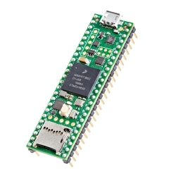
Arduino Pro Mini 328 - 5V/16MHz
SparkFun's minimal design approach to Arduino. This is a 5V Arduino running the 16MHz bootloader.
 Hookup Guide
 Schematic
Product Overview
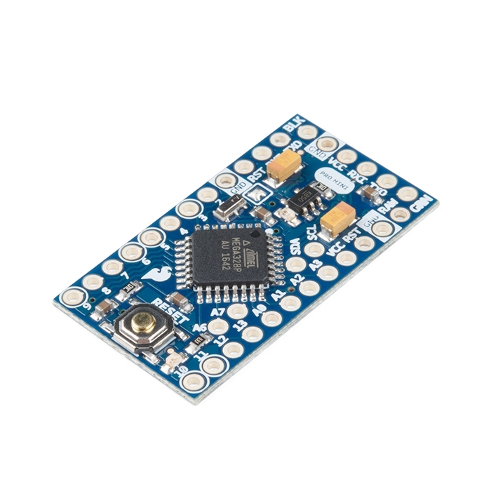
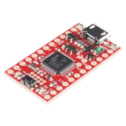
It's blue! It's thin! It's the Arduino Pro Mini! SparkFun's minimal design approach to Arduino. This is a 5V Arduino running the 16MHz bootloader. Arduino Pro Mini does not come with connectors populated so that you can solder in any connector or wire with any orientation you need. We recommend first time Arduino users start with the Uno R3. It's a great board that will get you up and running quickly. The Arduino Pro series is meant for users that understand the limitations of system voltage (5V), lack of connectors, and USB off board.
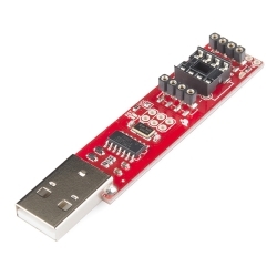
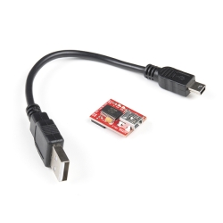
We really wanted to minimize the cost of an Arduino. In order to accomplish this we used all SMD components, made it two layer, etc. This board connects directly to the FTDI Basic Breakout board and supports auto-reset. The Arduino Pro Mini also works with the FTDI cable but the FTDI cable does not bring out the DTR pin so the auto-reset feature will not work. There is a voltage regulator on board so it can accept voltage up to 12VDC. If you're supplying unregulated power to the board, be sure to connect to the "RAW" pin and not VCC.
The latest and greatest version of this board breaks out the ADC6 and ADC7 pins as well as adds footprints for optional I2C pull-up resistors! We also took the opportunity to slap it with the OSHW logo.
Note: A portion of this sale is given back to Arduino LLC to help fund continued development of new tools and new IDE features.
Dimensions: 0.7x1.3" (18x33mm)
Features:
- ATmega328 running at 16MHz with external resonator (0.5% tolerance)
- 0.8mm Thin PCB
- USB connection off board
- Supports auto-reset
- 5V regulator
- Max 150mA output
- Over current protected
- Weighs less than 2 grams!
- DC input 5V up to 12V
- On board Power and Status LEDs
- Analog Pins: 8
- Digital I/Os: 14
Documents:


-
-
-
 SparkFun PIR Breakout - 170uA (EKMC4607112K)
Special Price Current price: $12.90 Regular Price Original price: $21.50In stock
SparkFun PIR Breakout - 170uA (EKMC4607112K)
Special Price Current price: $12.90 Regular Price Original price: $21.50In stock -
 SparkFun PIR Breakout - 1uA (EKMB1107112)
Special Price Current price: $14.95 Regular Price Original price: $32.50In stock
SparkFun PIR Breakout - 1uA (EKMB1107112)
Special Price Current price: $14.95 Regular Price Original price: $32.50In stock -
-
-
-
-
-
-
-
-


Features & Specs
- ATmega328 running at 16MHz with external resonator (0.5% tolerance)
- 0.8mm Thin PCB
- USB connection off board
- Supports auto-reset
- 5V regulator
- Max 150mA output
- Over current protected
- Weighs less than 2 grams!
- DC input 5V up to 12V
- On board Power and Status LEDs
- Analog Pins: 8
- Digital I/Os: 14
- 0.7x1.3" (18x33mm)
Documentation
Customer Reviews
