
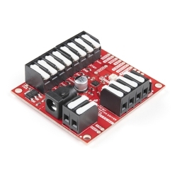
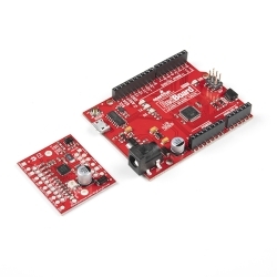
EasyDriver - Stepper Motor Driver
The EasyDriver is a simple to use stepper motor driver, compatible with anything that can output a digital 0 to 5V or 0 to 3.3V pulse.
Helpful Documentation
 Hookup Guide
 Schematic
 Datasheet (A3967)
Product Overview
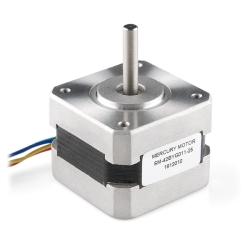
The EasyDriver is a simple to use stepper motor driver, compatible with anything that can output a digital 0 to 5V pulse (or 0 to 3.3V pulse if you solder SJ2 closed on the EasyDriver). The EasyDriver requires a 6V to 30V supply to power the motor and can power any voltage of stepper motor. The EasyDriver has an on board voltage regulator for the digital interface that can be set to 5V or 3.3V. Connect a 4-wire stepper motor and a microcontroller and you've got precision motor control! EasyDriver drives bi-polar motors, and motors wired as bi-polar. I.e. 4,6, or 8 wire stepper motors.
This EasyDriver V4.5 has been co-designed with Brian Schmalz. It provides much more flexibility and control over your stepper motor, when compared to older versions. The microstep select (MS1 and MS2) pins of the A3967 are broken out allowing adjustments to the microstepping resolution. The sleep and enable pins are also broken out for further control.
Note: Do not connect or disconnect a motor while the driver is energized. This will cause permanent damage to the A3967 IC.
Note: This product is a collaboration with Brian Schmalz. A portion of each sales goes back to them for product support and continued development.
Features:
- A3967 Microstepping Driver
- MS1 and MS2 pins broken out to change microstepping resolution to full, half, quarter and eighth steps (defaults to eighth)
- Compatible with 4, 6, and 8 wire stepper motors of any voltage
- Adjustable current control from 150mA/phase to 700mA/phase
- Power supply range from 6V to 30V. The higher the voltage, the higher the torque at high speeds
Documents:
- Schematic
- Eagle Files
- Hookup Guide
- Datasheet (A3967)
- EasyDriver Website
- Example Arduino Tutorial in Portuguese
- GitHub
-
-
-
-
-
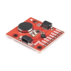
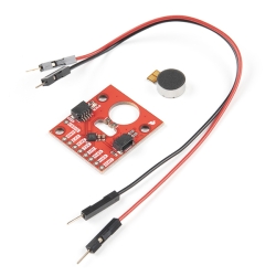 SparkFun Qwiic Haptic Driver Kit - DA7280
Special Price Current price: $10.50 Regular Price Original price: $17.50Discontinued
SparkFun Qwiic Haptic Driver Kit - DA7280
Special Price Current price: $10.50 Regular Price Original price: $17.50Discontinued -
-
-
-
-
-
-


Features & Specs
- A3967 Microstepping Driver
- MS1 and MS2 pins broken out to change microstepping resolution to full, half, quarter and eighth steps (defaults to eighth)
- Compatible with 4, 6, and 8 wire stepper motors of any voltage
- Adjustable current control from 150mA/phase to 700mA/phase
- Power supply range from 6V to 30V. The higher the voltage, the higher the torque at high speeds
Documentation
- Schematic
- Eagle Files
- Hookup Guide
- Datasheet (A3967)
- EasyDriver Website
- Example Reviews
Customer Reviews

Stock and Customer Discounts
Available Discounts
- $17.58 | 10+ units
- $16.65 | 25+ units
- $15.73 | 100+ units