SparkFun Qwiic Quad Relay
The SparkFun Qwiic Quad Relay is a unique power accessory board, used for switching 4 high powered devices from your Arduino or microcontroller using I2C.
Helpful Documentation
 Hookup Guide
 Schematic
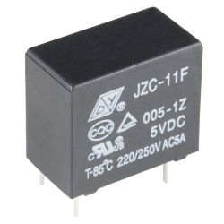
 Datasheet (JZC-11F)
Product Overview
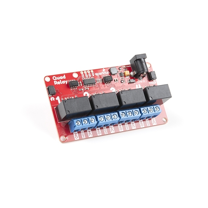
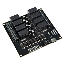
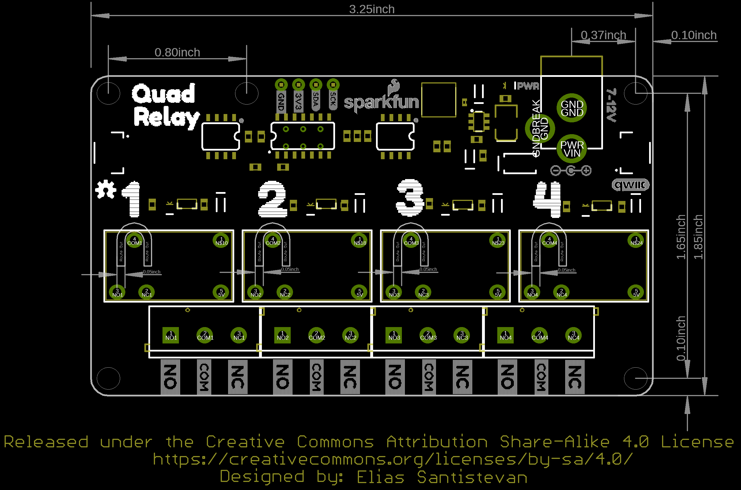
The SparkFun Qwiic Quad Relay is a unique power accessory board that has been designed for switching not one but four high powered devices from your Arduino or another low powered microcontroller using I2C. Taking a look at the board, the Quad Relay has four individual relays rated up to 5 Amps per channel at 250VAC or 30VDC. Each channel also has its own uniquely colored LED, silk for easy identification, and screw terminals for optional connection. Utilizing our handy Qwiic system, no soldering is required to connect it to the rest of your system!
At the heart of the SparkFun Qwiic Quad Relay is an ATtiny84 that takes various commands to toggle the four relays. The I2C address of the ATtiny84A is software configurable so if you had the desire and power, you could daisy chain over 100 Qwiic Quad Relays. There is also a header that breaks out the four I2C lines if you're not taking advantage of the Qwiic connectors. And last up, the barrel jack is rated for wall adapters in the range 7-12V but we have equipped this relay board with a jumper on the underside of the board if you want to use wall adapters at 5V.
Messing with such high voltage is dangerous! We've included many safety precautions onto the PCB including, wide traces designed for high amperage, ground isolation between the relay and other circuitry, and a milled out area around the common pin of the relay. However, with all the safety precautions included with the SparkFun Qwiic Quad Relay, this is still a power accessory for users who are experienced around, and knowledgeable about high AC voltage. If that's not quite your jam, that's okay! Check out the IoT Power Relay, instead, to start learning how to use power relays easily!
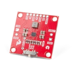
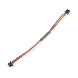
The SparkFun Qwiic Connect System is an ecosystem of I2C sensors, actuators, shields and cables that make prototyping faster and less prone to error. All Qwiic-enabled boards use a common 1mm pitch, 4-pin JST connector. This reduces the amount of required PCB space, and polarized connections mean you can’t hook it up wrong.
-
-
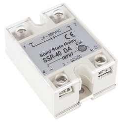
 SparkFun Qwiic Dual Solid State Relay
Special Price Current price: $59.95 Regular Price Original price: $149.95In stock
SparkFun Qwiic Dual Solid State Relay
Special Price Current price: $59.95 Regular Price Original price: $149.95In stock -
-
-
-
-
-
-
-
-


Features & Specs
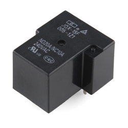
- Four JZC-11F Relays
- 5A at 250VAC, 30VDC
- Each relay has its own colored LED and silk labels for easy identification.
- Safey Features
- Ground pour isolated from relays.
- Air gap around common pin on the relays.
- Large trace width on relay pins far exceeding the peak 5A current.
- ATtiny84A
- I2C commands for toggling individual relays or all the relays at once.
- I2C commands for turning all relays off or on.
- Two I2C addresses
- 0x6D (Default)
- 0x6C
- I2C address is software configurable.
- All commands are listed in the example code.
- Screw Terminals
- 26-14 Gauge AWG wire
- Power
- Max Current Draw ~250mA
- Vin via Barrel Jack
- 7V to 12V
- Vin via Barrel Jack w/ Bypass Jumper Closed
- 5V
Revision Changes: The latest revision includes the following updates.
- Included a normally closed jumper for the power LED.
- Switching regulator in place of a linear regulator.
- The switching regulator is much more efficient; no external cooling needed when powering four relays at once.
- Improved circuitry around the relays.
- An issue where relays on certain boards in v1.0 didn't switch completely when actuated has been resolved.
Documentation
Customer Reviews

Stock and Customer Discounts
Available Discounts
- $33.20 | 10+ units
- $31.46 | 25+ units
- $29.71 | 100+ units