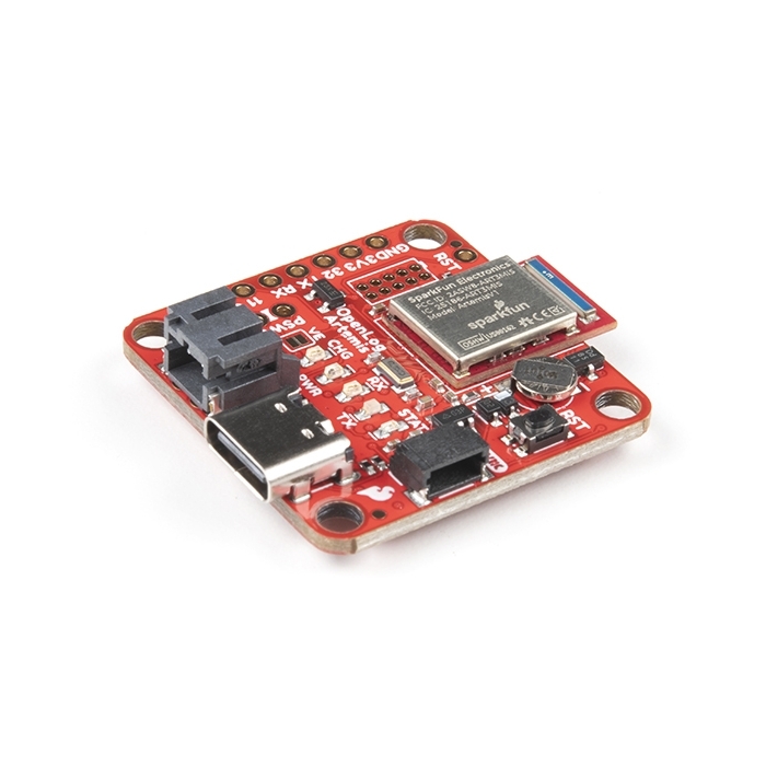
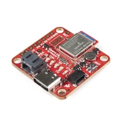
SparkFun OpenLog Artemis
The SparkFun OpenLog Artemis is an open source data logger that comes pre-programmed to automatically log IMU, GPS, serial data, and more.
Helpful Documentation
 Hookup Guide
 Datasheet (Apollo3)
 Schematic
Product Overview
We have stock of a new OpenLog Artemis (without IMU) available now!
Notice: Supply chain constraints have made the on-board ICM-20948 IMU very difficult to source. That said, we have a new version of the OpenLog Artemis available now with the IMU removed.
The SparkFun OpenLog Artemis is an open source data logger that comes preprogrammed to automatically log IMU, GPS, serial data, and various pressure, humidity, and distance sensors. All without writing a single line of code! OpenLog Artemis, or "OLA," automatically detects, configures, and logs Qwiic sensors. The OLA is specifically designed for users who just need to capture a lot of data to a CSV and get back to their larger project.
Included on every OpenLog Artemis is an IMU for built-in logging of triple-axis accelerometer, gyro, and magnetometer. Whereas the original 9DOF Razor used the old MPU-9250, the OpenLog Artemis uses the latest ICM-20948 from InvenSense capable of nearly 250Hz logging of all nine axes. Simply power up the OpenLog Artemis and all incoming serial data is automatically recorded to a log file with baud rates up to 500000bps [1], supported! The OLA also has four ADC channels available on the edge of the board. Voltages up to 2V can be logged with 14-bit precision up to 1900Hz for one channel and 1000Hz logging all four channels. Additionally, based on feedback from users we've added an on-board RTC so that all data can be time stamped.
The OpenLog Artemis is highly configurable over an easy to use serial interface. Simply plug in a USB-C cable and open a terminal at 115200bps. The logging output is automatically streamed to both the terminal and the microSD. Pressing any key will open the configuration menu.
The OpenLog Artemis automatically scans, detects, configures, and logs various Qwiic sensors plugged into the board (No soldering! No programming!). Currently, auto-detection is supported on the following Qwiic products:
- Any u-Blox GPS Modules (Lat/Long, Altitude, Velocity, SIV, Time, Date) such as:
- MCP9600 Thermocouple Amplifier
- NAU7802 Load Cell Amplifier
- LPS25HB Barometric Pressure Sensor
- BME280 Humidity and Barometric Pressure Sensor
- MS5637 Barometric Pressure Sensor
- MS5837 Depth and Pressure Sensor
- SDP31 Differential Pressure Sensor
- MS8607 Pressure Humidity Temperature Sensor
- MPR0025PA MicroPressure Sensor
- TMP117 High Precision Temperature Sensor
- AHT20 Humidity and Temperature Sensor
- SHTC3 Humidity and Temperature Sensor
- CCS811 Air Quality Sensor
- SGP30 Air Quality Sensor
- SGP40 Air Quality (VOC Index) Sensor
- SCD30 CO2 and Air Quality Sensor
- SN-GCJA5 Particle Sensor
- VEML6075 UV Sensor
- VCNL4040 Proximity Sensor
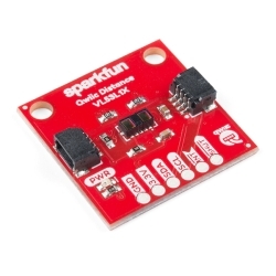
- VL53L1X LIDAR Distance Sensor
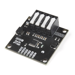
- ADS122C04 ADC PT100 Sensor
- Qwiic Mux allowing for the chaining of up to 64 unique buses!
- MAX30101 Pulse Oximeter and Heart Rate Sensor
- ISM330DHCX IMU
- MMC5983MA Magnetometer
- KX134 Accelerometer
- ADS1015 ADC
- LPS28DFW Barometer
- VEML7700 Ambient Light Sensor
- TMP102 Temperature Sensor
- More boards are being added all the time!
This OpenLog uses common microSD cards to record clear text, comma separated files. You probably already have a microSD card laying around but if you need any additional units see the related items below. The OpenLog Artemis supports microSD cards formatted as FAT32 as well as the older FAT16 formats up to 32GB. The OpenLog Artemis can use any size microSD card and, as of firmware version 1.11, supports exFAT cards in addition to FAT32.
Very low power logging is supported. OpenLog Artemis can be configured to take readings at 500 times a second, or as slow as 1 reading every 24 hours. You choose! When there is more than 2 seconds between readings OLA will automatically power down itself and the sensors on the bus resulting in a sleep current of approximately 18uA. This means a normal 2Ah battery will enable logging for more than 4,000 days! OpenLog Artemis has built-in LiPo charging set at 450mA/hr.
New features are constantly being added so we’ve released an easy to use firmware upgrade tool. No need to install Arduino or a bunch of libraries, simply open the Artemis Firmware Upload GUI, load the latest OLA firmware, and add features to OpenLog Artemis as they come out!
The OLA can be tailored to many different applications and we will be releasing custom versions of the firmware which can be found on our Documents tab above.
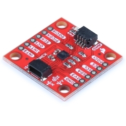
The SparkFun Qwiic connect system is an ecosystem of I2C sensors, actuators, shields and cables that make prototyping faster and less prone to error. All Qwiic-enabled boards use a common 1mm pitch, 4-pin JST connector. This reduces the amount of required PCB space, and polarized connections mean you can’t hook it up wrong.


Features & Specs
- Artemis Module (Cortex-M4F based Apollo3 microcontroller)
- Configurable via CH340E and Artemis Firmware Upload GUI
- Operating voltage range
- 3.3V to 6.5V (via VIN with optional external power switch)
- 5V with USB (via 5V or USB type C)
- 3.6V to 4.2V with LiPo battery (via VBATT or 2-pin JST)
- Built-in MCP73831 single cell LiPo charger
- Minimum 450mA charge rate
- 3.3V (via 3V3)
- Current consumption
- ~20mA (Run)
- ~80µA (Sleep)
- ~18µA (Deep Sleep - regulator shut down)
- Ports
- 1x USB type C
- 1x LiPo battery enabled
- 1x Qwiic enabled I2C with power control
- 1x SWD 2x5 header
- 4x Analog-to-digital
- 14-bit, up to 1900Hz, 2V max (3.3V compatible)
- Serial
- Logging speeds up to 500000bps [1]
- 1x microSD socket
- Support for FAT32 and older FAT16 formats up to 32GB with power control
- RTC with 1mAhr battery backup
- 9-axis IMU logging up to 250Hz
- ICM-20948 via SPI interface
- LEDs
- Power
- LiPo charge indicator
- Serial Tx and Rx
- Status
Documentation
- Schematic
- Eagle Files
- Hookup Guide
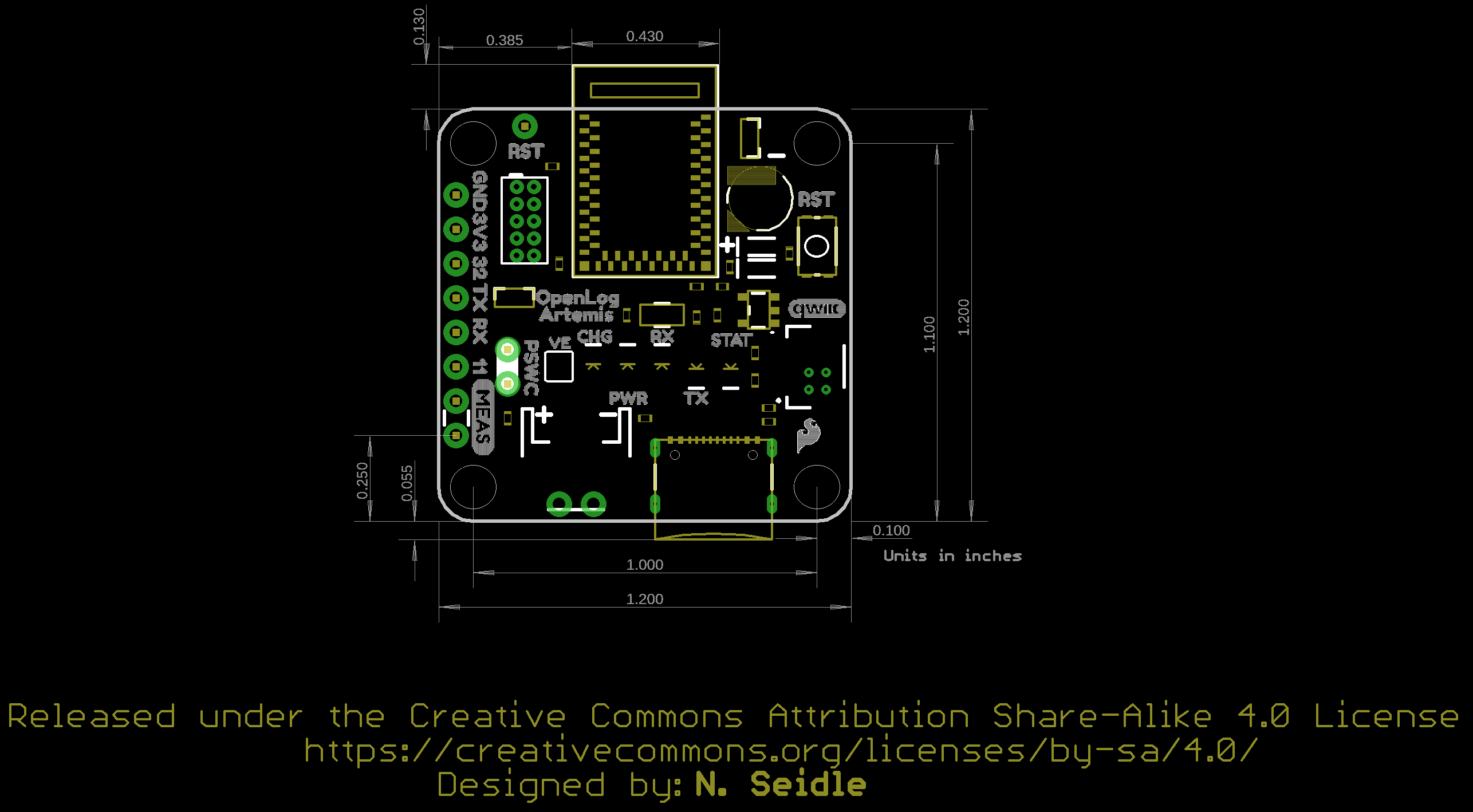
- Board Dimensions
- Datasheet (Apollo3)
- Datasheet (ICM-20948)
- Artemis Integration Guide
- Designing with the SparkFun Artemis
- Artemis Development with Arduino
- Arduino Core
- Artemis Forums
- Artemis Info Page
- Qwiic Info Page
- CH340E USB Drivers
- Artemis Firmware Uploader GUI
- Latest OLA firmware: v1.11
- Geophone Logger firmware for logging seismic activity
- GNSS Logger for advanced data logging with the uBlox F9 and M9 GNSS modules including support for RAWX and RELPOSNED
- GitHub Hardware Repo
Customer Reviews
Stock and Customer Discounts
Available Discounts
- $56.95 | 10+ units
- $53.96 | 25+ units
- $50.96 | 100+ units