
For this blog post, I was originally going to write a survey of some of my favorite tools - things that my workbench would be incomplete without. As I wrote more, I found that I'd written a whole lot about one specific tool. Rather than deleting it and starting over, I decided to change the subject.
If [SFUptownMaker <3 Python](https://www.sparkfun.com/news/1304), *I .LT.3 SPICE*.
That's a FORTRAN 77 joke for the uninitiated.
SPICE is circuit simulation software that allows you to quickly and easily see how a circuit performs. It's a virtual workbench with electronic components and test equipment that helps me jumpstart the design process.
History
SPICE (Simulation Program with Integrated Circuit Emphasis) originated at UC Berkeley in the 1970s. It is a circuit simulation program that was initially intended to simulate the internal details of integrated circuits, but it's also useful for more general circuit design applications.
The original Berkeley versions were a UNIX command-line based application. Schematics were entered in a text form, in a file called a netlist. It described all of the components and the electrical connections between them. I found them to be really cumbersome - I had to draw the schematic on paper, and then meticulously translate it into a netlist. If I did it successfully, I could hope to get an ASCII plot of the output.
V1 0 v- 12
V2 v+ 0 12
V3 Vgen 0 PULSE(-1 1 .5 1u 1u .5m 1m 1000) AC ac 1.
XU1 N002 Vout v+ v- Vout level.2 Avol=1Meg GBW=10Meg Slew=10Meg ilimit=25m rail=0 Vos=0 phimargin=45 en=0 enk=0 in=0 ink=0 Rin=500Meg
R1 N001 Vgen 10k
R2 N002 N001 10k
C1 Vout N001 10n
C2 N002 0 10n
.tran 2
;ac oct 12 10 20k
.lib UniversalOpamps2.sub
Sample ASCII Netlist
Newer SPICE packages take advantage of graphical user interfaces. You can draw a schematic, then interact with it in a virtual test bench environment. There are many circuit simulators around, ranging from free to extremely expensive. A few of the free ones I've used include.
- Texas Instruments Tina
- Curcuitlab.com, an online simulator, which runs in your browser
- Linear Technology LTspice
I'm most familiar with LTspice, so I'm going to base this brief example on it. LTspice was originally known as SwitcherCAD, intended as an aid for switch-mode power supply design. It proved to be useful enough in other areas that it has been renamed, and the library of components expanded to cover more general parts.
If you'd like to follow along, begin by downloading and installing LTspice from Linear Tech's downloads page.
A Quick Walkthrough
First, forget everything you know about editing schematics in your PCB software. The schematic drawing tool is almost entirely different, and involves a bit of a learning curve - if I really stepped through creating a circuit, there wouldn't be much room left to discuss what you can do with it.
Instead of starting from scratch, I've posted a sample schematic on my Github page. I'll also leave some tidbits below that will make learning to use it a bit easier.
Please download the sample, and open the file sallen-key.asc in LTspice.
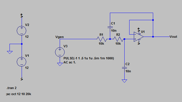
Sample SPICE schematic
This schematic contains a simulation of an equal-value Sallen-Key lowpass filter. One the left are voltage sources forming a bipolar 12VDC supply. In the middle is a voltage source acting as an AC signal generator, configured to produce a one-second long burst of a 1 kHz square wave. On the right is a single opamp, with resistors and capacitors to configure it as a lowpass filter.
SPICE operates in several different modes, depending on how we want to approach a problem. Let's explore a couple of those modes.
Virtual Oscilloscope
The simplest mode of operation for LTspice is as a virtual oscilloscope, known as transient analysis.
If you hit the "run" button on the toolbar, the simulation will run, and a new window will open...but it's empty!
This is where the simulation acts like a vitrual oscilloscope. If you go back to the schematic window and hover over a wire in the simulation, you'll see that the cursor becomes a little scope probe.
If you click that probe on a wire, the voltage on that wire gets added to the waveform window. For this simulation, click on the wires labeled Vgen and Vout. You'll see something like this.
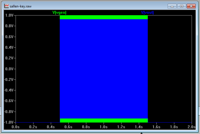
This is zoomed out significantly. You can use the magnifying glass tools to zoom in, and discover that those colored rectangles are actually waveforms.

Input versus Output waveforms
Here we can see that Vgen is a square wave, and Vout is a rounded-off version of that wave, as the high frequency harmonics have been removed from the square.
Virtual Specturm Analyzer
A second mode of operation is as a spectrum analyzer, which is useful to show our filters frequency response.
Leaving the waveform window open, right-click on the schematic, and select the Edit Simulation Cmd. menu option. Select the AC Analysis tab, and close the dialog.
Now run the simulation again. The waveform display is replaced by plot of amplitude versus frequency.

Here, the AC voltage source has been reconfigured as a reference signal generator. The simulation steps the generator through a frequency range, records the node voltages at each frequency. We see confirmation that the high frequency of the output is reduced relative to the input.
By clicking on the V[vout] trace name at the top of the plot, we get a set of crosshairs that track the plot, allowing us to make more detailed measurements. The crosshairs show us that the filter output is 3 dB down at 1,023 Hz.
Some Shortcuts
Rather than performing an extensive tutorial of all of the workings and capabilities of LTspice, I'll leave that as an exsecise for the reader.
Instead, I'll share some of the things I wish I'd known when I was getting started.
- To place passive components, the common symbolic letter is a shortcut for it:
- "r" for resistors.
- "c" for capacitors.
- "l" for inductors.
- Other components are found in the menu under the and gate button in the toolbar (or F2).
- To rotate a component, use control+r.
- LTspice understands a variety of component value shorthand notation
- The units are usually implied by the type of component you're working with
- Resistors are in Ohms
- Capacitors are in Farads
- Inductors are in Henries
- You can suffix the value with metric prefixes - the most commonly used would be
- "k" for kilo.
- "u" for micro.
- "n" for nano.
- "p" for pico.
- Mega and milli are a bit counter-intuitive
- The suffix "m" means "milli," one thousandth.
- Use the suffix "Meg" for millons
- You can use US-style (2.2K) or European-style (2K2) decimal notation.
- The units are usually implied by the type of component you're working with
- Secondary parameters (equivalent series resistance on an inductor, for example) can be accessed by right-clicking on a component.
- Similarly, right-clicking on some parts will bring up a menu with specific models of that type of component. When I place a diode, it gives me a generic diode by default, but that menu lets me turn it into a 1n4148.
- There's a lot accessed by right clicking, in general.
- Probes are applied to node names, and the schematic editor renumbers nodes in the background. If you simulate, then edit the schematic, and re-run the simulation, sometimes the nodes you were probing have been renamed, and the output no longer makes sense. You can avoid the renumbering by using the net label (F4) to assign an explicit name
- Copy is the icon with the pair of pages (or F6). It's a bit different from the regular Windows copy semantics.
- If you click on a component, it will copy only that component
- If you drag from empty space, you can use marquee-select to grab a group of components.
- Move (the hand with the splayed fingers, or F7) will move a component, and sever connections as it moves.
- Drag (the hand with the closed fingers, or F8) moves the component, but the wires will stay connected.
- A feature that I've found extremely useful for audio-related designs is the ability to use .wav files as input and output.
- LTspice comes with a default library of parts, mostly from LT. If you go hunting on the web, you can find many other models. The LTspice User's group on yahoo is a central resource for more component models.
Hangups
There's an old quote about circuit simulation, usually attributed to Robert Pease - "My favorite programming language is solder."
Simulation in general (not just limited to SPICE) runs the risk that the simulation doesn't correspond to real-world behavior. It doesn't simulate every aspect of a circuit, and the accuracy of the simulated components can vary quite a bit.
One of the classic tests for a SPICE simulation is to build an opamp circuit with a lot of gain, then feed it a large signal. Older opamp models would drive the output outside the rails, but this seems to be solved in modern models. Similarly, simulated resistors have no power ratings - they'll happily dissipate ludicrous amounts of power, where real resistors would smolder or scorch.
It helps to stay sensible. Double check datasheets, use the virtual ammeter probes, and apply downloaded models with a degree of suspicion - there could be a mistake in the model.
I don't jump right from the simulation to a completed design - it's a stepping stone to help understand circuit behavior. I can experiment with parts that may be expensive, unavailable, or hard to casually prototype with. I can evaluate whethera part of solution is appropriate, before moving to a real breadboard and prototype PCBs. Sometimes it takes work to figure out why the prototype behaves nothing like the model. I'm currently troubleshooting problems with a Schottky diode that seems to conduct backwards in the sim.
Ultimately, you have to actually build the circuit from real components to prove that it works.
In Actual Use
For the recent analog designs I've done for SparkFun, I used LTspice to help tune them. I've included the LTspice schematics in the respective GitHub repositries, usually in a sims/ or documentation/sims/ directory.
- Sound Detector
- VKey Voltage Keypad
- Others are pending - keep an eye open for them!
You'll have to wait until next time to find out why I keep 6 different kinds of wire strippers around, and which of them is my favorite.


On a related note, maybe SparkFun should have a circuit simulation forum, and somewhere on GitHub to host Spice Models (or, at least, links TO Spice Models)? The pesky questions I’ve been asking about models for this and that in the Sparkfun forum are probably in a not-quite-right place, and would likely be better served in a forum specific to that topic.
The only thing not so great about Spice is when a component you need doesn’t have a model, or worse, has one, but ENCRYPTS it. That lp2985-33dbvr 3.3V regulator on the Arduino UNO and the Leonardo? It’s Spice model is encrypted by Texas Instruments, to only work with certain varieties of Spice simulator, of which LTSpice is not one. The MIC5205 doesn’t appear to have a simulation either. Being able to simulate the response of your regulator to your various ICs can be very important in debugging wonky behavior on your power rails.
While one could argue that Arduino’s priority on being learnable and hackable hardware, or Open Source Hardware’s priority on being open, should extend to simulation models, I think it would be a mistake to choose a component by whether or not it has a widely available simulation. It would solve the problems of more people to just use a better quality part, and request they release a Spice model after the fact. Fortunately, Texas Instruments has a process for this (one of at least a few examples: http://e2e.ti.com/support/development_tools/webench_design_center/f/234/t/300299.aspx), so if we politely make a point, we might be able to get the model for that pesky lp2985-33dbvr regulator.
Perhaps a certain SparkFun staffer would prefer to make the case for such a request by posting in the TI forum below? :) http://e2e.ti.com/support/development_tools/webench_design_center/f/234.aspx
Excellent article. I love LtSpice!
Re-reading this a day after writing it, I'm all too aware that I missed my opportunity to make a Guild Steersman joke.
One geek demerit for me.
Yenka (used to be Crocodile Clips) - free for home use on one PC (with time restriction between 8:30 and 3:30 Mon-Fri), not free for every other use. If memory serves correctly, resistors do fry. The downside to this program is the lack of components. You can simulate PIC and PICAXE with flowcharts. But you won't find any ROM nor RAM. I've used it to figure out why most of my circuit designs didn't work correctly.